


SKY
-
5
-
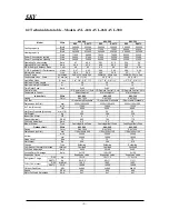
2.1 Technical data table – Models AVL-200, AVL-220
AVL-200 AVL-220
Model 50Hz
R22 R407C R22 R407C
Btu/h 193400
190000
217000
213000
Cooling capacity
Watt 56682
55684 63599 62425
Btu/h 194600
191080
218800
213240
Heating capacity
Watt 57034
56000 64127 62500
Power Consumption cooling
Watt
23000
22600
25500
25100
Power Consumption Heating
Watt
22000
22200
24300
24100
Operating Current cooling
Amp
38.6
38.2
42.8
42.3
Operating Current Heating
Amp
37
37.2
40.8
40.4
E.E.R-Energy Efficiency Ratio
Cool
8.4
8.4
8.5
8.5
C.O.P-Coefficient Of Performance
Heat
2.6
2.52
2.64
2.64
Moisture Removal
Lit/h
24
24
2.3
26.3
Power Supply
Volt/Hz/ph
380/415V, 50Hz, 3ph
380/415V, 50Hz, 3ph
Condensate Lines - Drain
Ф
- mm (in)
29 (1 1/8")
29 (1 1/8")
Liquid/Gas Lines
Ф
- inch
1/2", 7/8" ; 1/2",7/8"
1/2", 7/8" ; 5/8", 1
⅛
"
Maximum Piping Length
m.
30
30
Maximum Height Difference
m.
12
12
Time Delay Fuse
Amp.
3x63
3x63
Control Mode
I.R. Remote Control / Auto I.R. Remote Control / Auto
Temperature Control
Microcomputer
Microcomputer
Indoor Unit
50Hz
AVL-200
AVL-220
Casing
Color
RAL 7032
RAL 7032
Air Filter
1 Removable/Washable
1 Removable/Washable
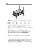
Dimensions (LxDxH)
mm
2050x1000x800
2050x1000x800
m
3
/h 10880
12240
Air Flow (Nominal)
cfm 6400
7200
Net Static Pressure (Nominal)
mm H
2
O 25
25
Net Weight
Kg.
240
245
Indoor Fan Motor:
HP
3
3
Speed (Nominal)
R.P.M
900
890
Full Load Amperage
Amp.
4.8
4.8
Blower Wheel
Type
Centrifugal-Belt Drive
Centrifugal-Belt Drive
Outdoor Unit
50Hz
AVL-200
AVL-220
Casing
Color
RAL 7032
RAL 7032
Dimensions (LxDxH)
mm
1700x1660x1000
1700x1660x1000
m
3
/h 38800
36800
Air flow
cfm 22400
21400
Noise Level
dba
72
72
Net Weight
Kg.
500
533
Fittings Type
Flare
Soldering
Compressor Thermal Protection
Internal
Overload
Overload
Full Load Amperage
Amp.
2x17
17+22
Locked Rotor Amperage
Amp.
2x10⁵
105+130
Expansion Device
Expansion valve
Expansion valve
R22 Kg.
8.1+8.1
8.1+10
Refrigerant Charge
R407C Kg.
7.5+7.5
7.5+9.3
R22 Mineral
160P
160P
Oil for Compressor
R407C P.O.E
160ZE
160ZE
Outdoor Fan Motor
KW
4x0.66
4x0.66
Speed
R.P.M
900
900
Motor Full Load Amperage
Amp.
4x1
4x1
Summary of Contents for AVL-200
Page 9: ...SKY 9 4 Refrigeration Cycle...
Page 12: ...SKY 12 6 Electrical Wiring Diagram...
Page 13: ...SKY 13...
Page 14: ...SKY 14 NOTES...
Page 22: ...SKY 22 NOTES...
Page 32: ...SKY 32 NOTES...
Page 35: ......
Page 36: ...EN POWER SKY AVL AVR 200 300 V01 R01 JUN 2005...


