PKIR, PKIS
| PP-28_201612 | 39 / 48
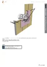
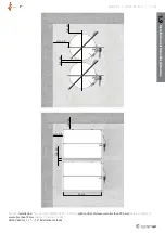
threaded rods (1) min. M10.
4. (Applies only to PKIR3G and PKIS3G)
Insulate the damper and duct parts between the damper and
the wall. Glue the insulation onto the wall using suitable glue
(e.g. BSK, ISOVER). Secure the insulation (9, 10) with density
of 66 kg/m
3
onto the square duct in two 90 mm layers using
90 mm (1st level) and 180 mm (2nd level) long welding pins
(11, 12). Bind the round damper part and duct insulation with
a binding wire (ø 1,6 mm) in the usual way that is applied
when insulating round ducts.
5. (Applies only to PKIS-EI90S)
Insulate the damper and duct parts between the damper and
the partition structure. Glue the insulation onto the partition
wall using suitable glue (8; e.g. BSK, ISOVER). Secure the
insulation (9, 10) with density of 66 kg/m
3
onto the rectan
-
gular duct in two 100 mm layers using 100 mm (1st level)
and 200 mm (2nd level) long welding pins (11, 12).
6. Cover the insulation face and perimeter up to a distance
of 150 mm from the insulation corner using galvanized sheet
(13) with width at least 0,9 mm (it is possible to order
a finished insulation face cover – IPOR-PKI/IPOS-PKI instal-
lation accessories – see TPI-28), secure the sheet against
the damper housing only on the sides parallel to the damper
axis (only applies to PKIS3G) using self-drilling screws with
max. gaps of 200 mm (14, recommended screw diameter
3,9 × max.13 - for example DIN7504). Any protruding screws
which could stand in the way of the blade during its opening
need to be shortened to align with the housing interior.
7. If needed, uncover and clean the damper after installation.
8. Check the damper functionality.
1.6.3
INSTALLATION
OUT OF A WALL
EI90S
- using promatect boards (Fig. 15c)
This installation can be used with
L
D
≤ 1500 mm for fire dampers
as per Tab. 1 and 2.
For a rectangular damper a rectangular opening with dimensions
W
+ 120mm and
H
+ 120mm (as per Fig. 2 and 4 and Tab. 23),
the opening surfaces must be even and cleaned off.
The opening in the flexible wall must be reinforced as per the
standards for plasterboard walls.
NOTES (chapters 1.5 and 1.6):
1. It is possible to use the wet method for duct installation into
a wall – by plaster / mortar / concrete instead of Positions 4
through 8.
2.
For
L
D
> 1500 mm the maximum spacing between threaded
rods must be 1500 mm and one more point of suspension
must be added as close as possible to the connection flange
on the blade side.
1.6.4
INSTALLATION
OUT OF A WALL
EI60S - using
promatect boards (Fig. 15d)
This installation can be used with
L
D
≤ 1500 mm for fire dampers
as per Tab. 1 and 2.
For a rectangular damper a rectangular opening with dimensions
W
+ 120mm and
H
+ 120mm (as per Fig. 2 and 4 and Tab. 24),
the opening surfaces must be even and cleaned off. The opening
in the flexible wall must be reinforced as per the standards for
plasterboard walls.
PROCEDURE FOR
1.6.3
AND
1.6.4
Damper preparation for installation:
Attach IKOWS-PKI accessories around the perforation, as shown
in Fig. 15e and apply a suitable fire-resistant mastic (pos. 6; e.g.
Promat Kleber K84) to the contact surfaces of the boards and the
damper. Fasten them together using the screws included in the
1.6.2
INSTALLATION
OUT OF A WALL
EI60S
- using mineral wool (Fig. 15b, 15ba)
This installation can be used with
L
D
≤ 1500 mm for fire dampers
as per Tab. 1 and 2.
For the installation of a round damper, prepare a round opening
with a diameter of
DN
+ 120 mm, and for a rectangular damper a
rectangular opening with dimensions
W
+ 120 mm and
H
+ 120
mm (as per Fig. 1 through 4 and Tab. 21a and 22b). The opening
surfaces must be even and cleaned off. The opening in the flexi-
ble wall must be reinforced as per the standards for plasterboard
walls.
Damper preparation for installation:
(Applies only to PKIR3G): Fasten the round damper in the blade
and the perforation location with a suitable sheet metal ringlet
(3, e.g. MP-MX/ fa. HILTI) with the threaded rod M12 (1).
(Applies only to PKIS3G): Fasten the rectangular damper in the
blade / perforation location only on the top and bottom sides
with U-profiles (2, e.g. MQ31/fa. HILTI), and then fasten the U-
profiles together by using the threaded rod M10 (1).
Installation procedure:
1. Insert the duct into the load-bearing structure along with the
damper in such a way that the duct will stick out of the wall
in accordance with the distance needed. Press the 66 kg/m
3
insulation around the duct and cut its edges to even it with
the wall surface. Paint the insulation surface in alignment
with the wall with a suitable coat of paint (5 respect. 4; e.g.
BSF/fa. ISOVER) up to a distance of 100 mm from the duct in
order to cover the insulation and part of the wall.
2. (Applies only to PKIR3G): Reinforce the round duct from both
sides of the wall with the sheet metal ringlet (3, e.g. MP-MX/
fa. HILTI).
(Applies only to PKIS3G): Reinforce the rectangular duct with
crosses (8) along the insulated duct – the first cross is placed
in the wall, the others at distances of a max. 1000 mm.
3. (Applies only to PKIR3G): Insulate the damper and duct parts
between the damper and the wall. Entwine the round damper
and duct with insulation (6), with a density of 66 kg/m
3
in
one layer of 100 mm. Glue the insulation onto the wall using
a suitable glue (8 e.g. BSK, ISOVER). Secure the insulation (6)
with a binding wire (ø 1,6 mm) in the standard way that is
applied when insulating round ducts or by using wire clamps
(9) to sew together the meshes on the top of the insulati-
on (6). The actuator, thermosensor, and inspection lid must
remain uninsulated with a gap of a max.15 mm.
(Applies only to PKIS3G): Insulate the damper and duct parts
between the damper and the wall. Glue the insulation (6)
with a density of 66 kg/m
3
in one 80 mm layer onto the wall
around the duct by using a suitable glue (5 e.g. BSK, ISOVER).
Secure the insulation (6) using 80 mm long welding pins (7).
The actuator, thermosensor, and inspection lid must remain
uninsulated with a gap of a max.15 mm
4.
Around the front side and on all surfaces that are not covered
with aluminium foil, glue aluminium tape (7 respect. 9).
5. If needed, uncover and clean the damper after installation.
6. Check the damper’s functionality.


