36 / 48 | PP-28_201612 | PKIR, PKIS
Operating Conditions
Systemair fire dampers can be defined as fire shutters for
ventilation ducts in the place where they pass through walls or
ceilings, which are the borders of the fire area. In case of fire, the
dampers function as a fire safety element and by closing they
prevent the fire and smoke from expanding through the ventila-
tion duct during the defined time.
•
PKI fire dampers are designed for installations in accordance
with Tab. 1 and Tab. 2
•
All fire dampers are either manual or with an electric driving
mechanism as standard.
•
They are intended for installation in places which are protected
against weather disruptions in the ducts distributing air without
any mechanical or chemical contamination in the following
operating conditions:
•
Maximum air flow velocity 12 m/s
•
Storage temperature max. 50°C
This installation, operation and inspection manual applies
to PKIS fire damper types with fire resistance EI90S, EI120S,
PKIR3G, PKIS3G, PKIR60/90/120-Ex, PKIR3G-Ex, PKIS90/120-Ex,
PKIS3G-Ex.
This manual also applies to EKIR E60S evacuation dampers (in
the following text we will use the damper name if it concerns
both fire and evacuation dampers). The permitted installation
methods can be found in Tab. 1 and Tab. 2. This manual also
applies to fire dampers adjusted in accordance with the 94/9/EK
directive, which outlines the technical requirements for devices
and protection systems intended for usage in an area with
explosion risk – fire dampers are rated class II, category 2/-G for
protection against combustion of gases in explosion-proof class
IIB as per EN 13463-1:2009.
It contains basic information and recommendations regarding in-
stallation, usage and inspection, which must be followed in order
to ensure proper and trouble free damper operation. The key to
this is to read this manual thoroughly, use the damper as per the
instructions provided herein and follow the safety requirements.
Warnings
Some damper parts can have sharp edges – therefore it is neces-
sary to use gloves during damper installation and manipulation.
In order to prevent electric shock, fire or any other damage
which could result from incorrect damper usage and operation, it
is important to:
1. Install the damper in accordance with the installation manual
and by a properly trained employee.
2. Perform damper inspection in accordance with the mainte-
nance and inspection manual.
3. Before you can install the fire damper, it‘s functionality must
be checked as per chapter 3 (Fire Damper Functionality
Check). This procedure prevents installation of a damper that
has been damaged during transportation or handling.
Do not install non-functioning fire dampers!
The accessories:
- PRR-PKI, PRS-PKI coverplates for dry installation,
- CVR-PKI, CVRF-PKI, CVS-PKI compensators of the thermal
dilatation,
- MPC-PKI clutches,
- MPA-PKI adapters,
- RFA-PKI flanges for round dampers,
- SSAR-PKI, SSAS-PKI adapter with smoke sensor,
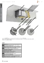
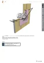
- IPOR-PKI, IPOS-PKI accessory for installation out of a wall and
on a wall
- IKOWS-PKI installation kit for installation out of a wall with
Promatect
- IKRR-PKI, IKRS-PKI and IKSS-PKI installation kits
(see TPI-28...) can be ordered along with the fire dampers.
In a standard design all manual and servomotor-operated fire
dampers are equipped with a thermal fuse which, after reaching
or exceeding 72 ± 2 °C, activates the spring which closes the
damper blade.
From the noise perspective all Systemair dampers are passive.
Increased noise can only be heard when the damper is being
closed or opened in case of inspection or fire (which lasts less
than 20 seconds).
1 Installation Manual
•
The duct connected to the fire damper must be supported or
hung in such way that the damper does not carry its weight.
The damper must not support any part of the surrounding
construction or wall which could cause damage and
consequent damper failure.
•
The damper driving mechanism can be placed on any side of
the wall, however it needs to be placed so as to ensure easy
access during inspection.
•
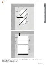
The distance between the fire dampers must be at least
60 mm - see chapter 1.9. This condition does not apply for
multiinstallation (point 1.7).
•
The distance between the wall / ceiling and the fire damper
must be at least 40 mm - see chapter 1.9.
•
The fire damper must be installed into a fire partition structure in
such way that the damper blade in its closed position is located
inside this structure. This condition does not apply for installation
on a wall or out of a wall under paragraphs 1.5 and 1.6.
•
The fire dampers can be installed into a wall or a ceiling with
minimum thickness as per EN 1366-2 and paragraph 1.8.
•
The gap in the installation opening between the fire damper
and the wall/ceiling can be increased by up to 50 % of the gap
area, or decreased to the smallest amount possible that still
provides sufficient space for the installation of the seal.
•
All dampers can be installed with the blade axis in a horizontal
or a vertical position in all installation methods except 1.5 on a
wall, 1.6 out of a wall and 1.7 multiinstallation.
•
The fire damper in a non-explosive version must be earthed
after being installed into the duct.
•
The design of a non-explosive electric device installed inside or
on a fire damper must correspond with the given surrounding
environment with an explosion risk as per EN 66079-10.
Below is a list of all permitted installation methods. Every me-
thod only applies to those damper types that are listed in the
corresponding paragraph’s heading. Methods that have the PKIS
and PKIR3G type listed in their heading are applicable for all the
damper types.


