38 / 48 | PP-28_201612 | PKIR, PKIS
1.5.1 - 1.5.4
INSTALLATION
ON A WALL
These installations are the same as when installing out of a wall
(see chapters 1.6.1 – 1.6.4) with following differences:
•
The distance of a rectangular damper’s ending as well as the
duct flange (the duct is installed in the wall) from the wall is
35 mm
•
The end of a round duct (installed in a wall) stays 1 mm out of
the wall surface adjacent to the damper.
1.6.1
INSTALLATION
OUT OF A WALL
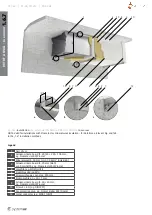
EI90S - using
mineral wool (Fig. 14, 15a)
This installation can be used with
L
D
≤ 1500 mm for fire dampers
as per Tab. 1 and 2.
For a round damper installation prepare a round opening with
diameter
DN
+ 120 mm, for a rectangular damper a rectangular
opening with dimensions
W
+ 120 mm and
H
+ 120 mm (as per
Fig. 1 through 4 and Tab. 20 and 21a), the opening surfaces must
be even and cleaned off. The opening in the flexible wall must be
reinforced as per the standards for plasterboard walls.
Damper preparation for mounting:
(Applies only to PKIR3G)
Fasten the round damper in the blade and perforation location
with ceramic adhesive tape (3, width 40 mm/thickness 2 mm)
and bind it up using a suitable sheet metal ringlet (2, e.g. MP-
MX/fa. HILTI).
(Applies only to PKIS3G)
Fasten the rectangular damper in the blade / perforation location
across the perimeter with calcium-silicate boards (3), 20 mm
thick, 60 mm wide (it is possible to also order it as part of IPOS-
PKI installation accessories, see TPI-28)and bind them up using
U-profiles (2, e.g. MQ31/fa. HILTI) and fasten them together
using threaded rods M10 (1).
(Applies only to PKIS-EI90S)
Mount a welded tubular profile (60 × 40 × 3 mm – it is possible
to also order it as part of IPOS-PKI installation accessories,
see TPI-28) hanging frame (15) onto the rectangular damper
part with blade / thermal barrier, the internal dimension of the
frame must be
W
+ 85 ×
H
+ 85 mm. Connect it to the damper
using sheet metals (16; dimension 85 × 40 × 2,5 mm with one
ø 6 mm opening on one side). For this purpose use the screws
(17), which fasten the damper’s thermal barrier.
Please note that you must not release all the screws at once.
It is always needed to release and secure the sheets one by one.
Such secured sheets can be connected to the Jäkl frame using
self-drilling screws (16; recommended screw diameter 3,9 ×
max. 13 - for example DIN7504). Do it around the entire perime-
ter in such way that for the nominal dimensions
up to
W
and
H
≤ 1000 mm there will be at least 3 sheets
and for
H
>1000 mm at least 4 units for each side.
Installation procedure:
1. Insert the duct into the load-bearing structure along with the
damper in such way that the duct will stick out of the wall to
the needed distance, which however needs to be less than
1500 mm from the wall - see the note 2 below this para-
graph. Press 66 kg/m
3
insulation around the duct (7) and cut
its edges to even it with the wall surface. Paint the insulation
surface in alignment with the wall with a suitable coat of paint
(8; e.g. BSF/fa. ISOVER) up to a distance of 100 mm from the
duct in order to cover the insulation and part of the wall.
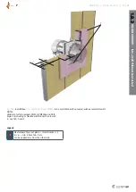
2. Attach the duct using rolled L-profiles (4; 40 × 40 × 3 mm,
length
W
+ 300) to the load-bearing structure using screws,
at least one on every end (5; recommended screw diameter
5,5 - for example DIN7981) and self-drilling screws against
the duct with maximum gaps of 200 mm (6; recommended
screw diameter 3,9 × max.13 - for example DIN7504). Attach
the round damper using L-shaped sheet metal consoles with
bracket sizes of 160 and 35 mm made from 40 mm sheet
metal belt evenly across the perimeter at 4 points. Use the
same screws as for a rectangular damper.
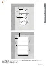
3. Hang the round damper onto a threaded rod (1) M12 using
the sheet metal ringlet (2) embedded in the blade location.
Hang the square damper, begirded in its perimeter with U-
profiles (2) or tubular frame, in the blade location onto the
1.4
INSTALLATION USING AN
INSTALLATION KIT
EI120S (Fig. 11, 12)
This installation can be used for fire dampers according to Tab.1 and 2.
1. For installation of a round damper prepare a round opening
of diameter
D
2
± 1 mm for solid wall, or
W
1
×
W
1
± 1 mm for
a
flexible wall, as per Tab. 19 and for a rectangular damper a
rectangular
opening with dimensions
W
+ 100 mm and
H
+
100 mm ± 1 mm (as per Fig. 1 through 4 and Tab. 17 and 18).
2. The opening in the flexible wall must be reinforced as per
the standards for plasterboard walls and the perimeter of its
interior must be lined with a double layer of 12,5 mm thick
plasterboard.
3. This is the simplest installation method. Insert the damper
into the opening and fix the front panel using appropriate
screws (recommended screw diameter 5,5 - for example
DIN7981) into pre-drilled holes.
4. If needed, uncover and clean the damper after installation.
5. Check the damper functionality.

