51/70 |
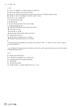
FDS...EX
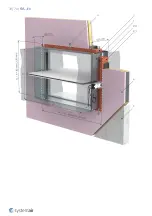
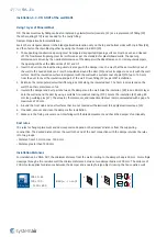
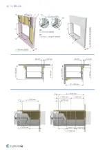
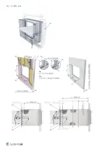
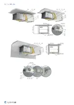
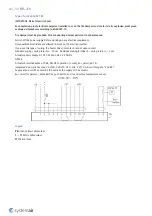
Installation, maximum, 5.3 - ON & OUT of the wall EI90S
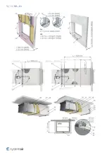
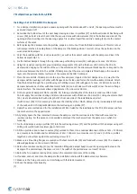
Using Promatect Boards
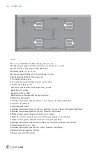
TIP: The duct-wall cavity filling (F12) and its coating (F13) can be also replaced by plaster/mortar/concrete (F2).
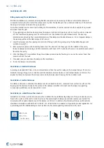
Damper Preparation before Installation:
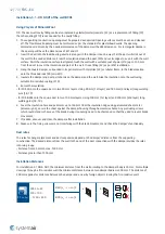
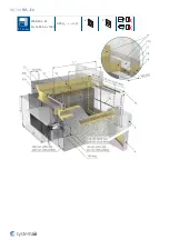
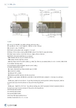
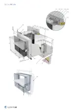
Attach all 4 parts of the IKOWS-FD accessory around the casing where the damper blade is situated, as shown in the
picture and apply a suitable fire-resistive coating (F13) to the contact surfaces of the boards and the damper. Fasten
them together using the screws included in the IKOWS-FD package.
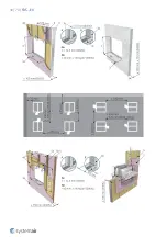
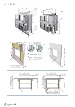
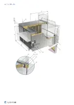
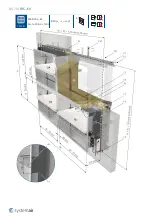
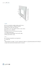
1. The supporting construction opening must be prepared as depicted. Opening surfaces must be even and cleaned
off. The flexible wall opening must be reinforced as per the standards for plasterboard walls. The opening
dimensions are driven by the nominal dimensions of the damper with added clearance. For rectangular dampers,
the opening will have the dimensions of W1 and H1.
2. Insert the duct into the load-bearing structure along with the damper in such a way that the duct will stick out of
the wall to the needed distance. Press the insulation around the duct (F12) and cut its edges to even it with the
wall surface.
3. Paint the insulation surface in alignment with the wall with a suitable coat of paint (F13) up to 100 mm from the
duct to cover the insulation and part of the wall. Or use filling (F2) as per WET installation.
4. Fit 4 boards (F15) of 100 mm in width around the duct and secure them to the wall using suitable screws (F1);
fasten an L-profile (F14) to the wall and the duct on the damper side; fasten 4 boards (32) by joining them
together in corners by screws.
5. Cover the IKOWS-FD accessory (A4) and the boards (32) along the entire length with 40 mm thick boards (31);
apply fire-resistive coating (F13) to all joints and fix with screws (33).
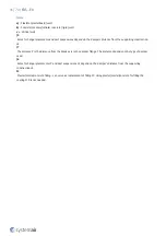
6. Bind the damper in the blade location using a profile (34) at the top and bottom damper side, using threaded rods
(20) and nuts. The threaded rods are to be at a distance of max. 50 mm from the side insulation surface.
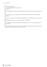
7. If needed, uncover and clean the damper after installation.
8. Make sure the fixing screws are not interfering with the blade movement and check the damper’s functionality.
Duct rules
The rules for hanger placement and duct suspension depend on the damper’s distance from the supporting
construction. The desired distance from the wall to the end of the duct connection with the damper divides the rules
into two groups:
• Distance from 35 mm to max. 1500 mm.
• Distance greater than 1500 mm.
Installation Distances
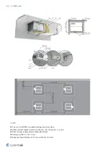
For installation 5.3 ON & OUT, the minimum distance from the wall or ceiling to the damper body is 40 mm. For multiple
crossings through a fire-resistive wall the minimum distance between two damper bodies is 200 mm. The distance of
200 mm applies for distances between the damper and a nearby foreign object crossing the fire-resistive wall.
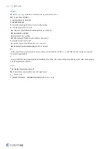
5.3
On, Out
FDS-3G...EX
100 × 100 ...
... 1200 × 800
EI 60 (v
e
- i ↔ o) S
a)
b)
EI 90 (v
e
- i ↔ o) S
Summary of Contents for FDS-3G EX Series
Page 1: ...FDS EX Atex Fire Damper ...
Page 8: ...8 70 FDS EX Product parts ...
Page 27: ...27 70 FDS EX ...
Page 30: ...30 70 FDS EX ...
Page 31: ...31 70 FDS EX ...
Page 35: ...35 70 FDS EX ...
Page 36: ...36 70 FDS EX ...
Page 39: ...39 70 FDS EX ...
Page 40: ...40 70 FDS EX ...
Page 43: ...43 70 FDS EX 5 1 On Out FDS EI90S EX W 1600 H 1000 EI 90 ve i o S a b ...
Page 44: ...44 70 FDS EX ...
Page 48: ...48 70 FDS EX ...
Page 49: ...49 70 FDS EX ...
Page 52: ...52 70 FDS EX ...
Page 53: ...53 70 FDS EX ...
Page 57: ...57 70 FDS EX 5 4 On Out FDS 3G EX 100 100 1200 800 EI 60 ve i o S a b ...
Page 58: ...58 70 FDS EX ...
Page 59: ...59 70 FDS EX ...
Page 63: ...63 70 FDS EX 7 Multi FDS EI90S EX W 1600 H 1000 EI 90 ve i o S b ...
Page 70: ...Systemair DESIGN 2021 04 27 Handbook_FDS_EX_en GB ...

