29/70 |
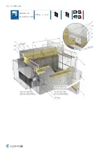
FDS...EX
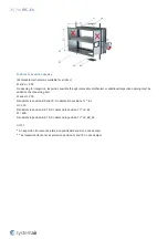
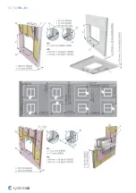
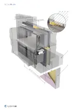
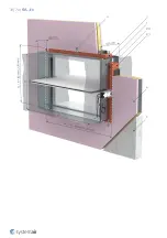
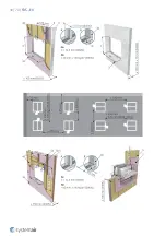
Installation 2 - Dry
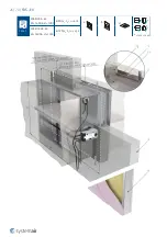
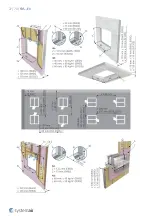
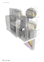
Using Mineral Wool and Cover Boards
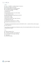
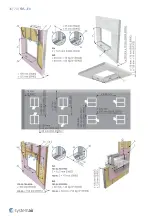
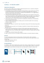
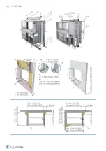
1. The supporting construction opening must be prepared as depicted. Opening surfaces must be even and cleaned
off. The flexible wall opening must be reinforced as per the standards for plasterboard walls. The opening
dimensions are driven by the nominal dimensions of the damper with added clearance. For rectangular dampers,
the opening will have dimensions of W1 and H1.
2. With FDS-3G dampers, it is necessary to install the bendable hangers (2) onto the cover boards using suitable
screws or screws with wall plug (F1).
With FDS-EI90S dampers, it is necessary to install the bendable hangers (2) onto the supporting construction
(below the cover boards) using suitable screws or screws with wall plug (F1). Insert the damper from the
mechanism side and secure the bendable hangers of the damper into the cover board (FDS-3G) or onto the wall
(FDS-EI90S) using suitable screws (F1). Subsequently mount the remaining cover boards from the mechanism side.
3. Fill in the area between the wall and the damper with mineral wool (F3) with a density of at least 50 kg/m3
thoroughly but in such a way that will not deform the damper housing, while paying attention to prevent the
fouling of the damper’s functional parts, which could limit its correct functionality.
4. Close the gap between the damper and the mounting opening, for a circular damper use CBR-FD cover boards, for a
rectangular damper use CBS-FD cover boards with screws (F1) through pre-drilled holes.
5. All the gaps between the cover boards, between cover boards and the wall and between cover boards and the fire
damper need to be filled with fire-resistive coating (F4).
6. If needed, uncover and clean the damper after installation.
7. Check the damper’s functionality
Installation Standard Distances
For Dry installation, the minimum distance from the wall or ceiling to the damper body is 150 mm. For multiple
crossings through a fire-resistive wall the minimum distance between two damper bodies is 300 mm. The distance
between the damper and a nearby foreign object crossing the fire-resistive wall is 200 mm.
Installation in a Wall thinner than tested
Installation in a thinner wall is allowed under the condition that an additional layer/layers of fire protective board are
fixed to the surface of the wall in order to achieve the same length of damper penetration seal as was tested. The
minimum width of added boards around the damper is 200 mm. In addition, the alternative thinner wall should be
classified in accordance with EN 13501-2:2007 + A1: 2009 for the fire-resistance required for product application. For
a protruding wall, the additional layers must be fixed on the steel supporting construction of the wall.
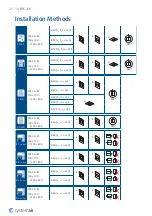
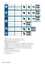
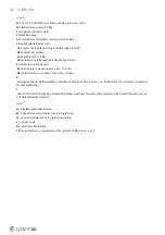
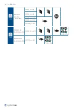
2 Dry
FDS-3G...EX
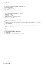
100 × 100 ...
... 1200 × 800
EI 60 (v
e
h
o
i ↔ o) S
a)
b)
c)
360°
EI 90 (v
e
h
o
i ↔ o) S
2 Dry
FDS-EI90S...EX
W ≤ 1600 & H ≤ 1000
EI 90 (v
e
h
o
i ↔ o) S
a)
b)
c)
*
≤ 1000 × 1000
Summary of Contents for FDS-3G EX Series
Page 1: ...FDS EX Atex Fire Damper ...
Page 8: ...8 70 FDS EX Product parts ...
Page 27: ...27 70 FDS EX ...
Page 30: ...30 70 FDS EX ...
Page 31: ...31 70 FDS EX ...
Page 35: ...35 70 FDS EX ...
Page 36: ...36 70 FDS EX ...
Page 39: ...39 70 FDS EX ...
Page 40: ...40 70 FDS EX ...
Page 43: ...43 70 FDS EX 5 1 On Out FDS EI90S EX W 1600 H 1000 EI 90 ve i o S a b ...
Page 44: ...44 70 FDS EX ...
Page 48: ...48 70 FDS EX ...
Page 49: ...49 70 FDS EX ...
Page 52: ...52 70 FDS EX ...
Page 53: ...53 70 FDS EX ...
Page 57: ...57 70 FDS EX 5 4 On Out FDS 3G EX 100 100 1200 800 EI 60 ve i o S a b ...
Page 58: ...58 70 FDS EX ...
Page 59: ...59 70 FDS EX ...
Page 63: ...63 70 FDS EX 7 Multi FDS EI90S EX W 1600 H 1000 EI 90 ve i o S b ...
Page 70: ...Systemair DESIGN 2021 04 27 Handbook_FDS_EX_en GB ...

