background image

24/70 | 

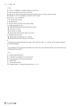
FDS...EX

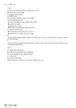
Rectangular fire dampers are certified according to EN 15650, tested according to EN 1366-2, classified according to 
EN13501-3 and explosion-proof certified according to Directive 2014/34/EU and EN ISO 80079-36.2016 - reached 
classes are: II 2 D Ex h IIIB T85°C...T100°C Db, II 2 G Ex h IIB T6...T5 Gb. For activation type H2-EX the temperature class 
is reduced to T85°C Db and T6 Gb.

IMPORTANT: The device must be installed in such a way that forming of creeping discharges is prevented (static 
surface charging).

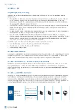
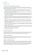
Installation, Maintenance & Operation

Some damper parts may have sharp edges – therefore to protect yourself from harm, please use gloves during damper 
installation and manipulation. In order to prevent electric shock, fire or any other damage which could result from 
incorrect damper usage and operation, it is important to:
1. ensure that the installation is performed by a trained person.
2. closely follow the written and depicted instructions provided within the Handbook.
3. perform a damper inspection in accordance with the Handbook.
4. check the damper’s functionality as per the chapter “Fire Damper Functionality Check” before you install the fire 

damper. This procedure prevents the installation of a damper that has been damaged during transportation or 
handling.

Information about installation, maintenance and operation is available in the “Handbook_FDR-3G” document or more 
can be found at SystemairDESIGN.

Installation rules

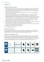
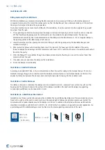
• The duct connected to the fire damper must be supported or hung in such a way that the damper does not carry its 

weight. The damper must not support any part of the surrounding construction or wall, which could cause damage 
and resulting damper failure. It is recommended to connect the damper to a dilatation compensator on either end of 
the damper.

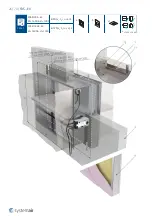
• The damper driving mechanism can be placed on either side of the wall, however, it needs to be placed so as to 

ensure easy access during inspection.

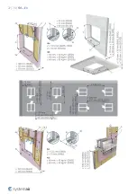
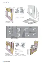
• According to standard EN 1366-2, the distance between the fire damper bodies must be at least 200 mm. This 

condition does not apply for tested distances. Therefore Wet and Soft installations are approved for smaller distances 
under the condition that the resulting resistivity is reduced to EI90S.

• The distance between the wall/ceiling and the fire damper must be at least 75 mm. This condition does not apply for 

tested distances. Therefore Wet and Soft installations are approved for smaller distances under the condition that the 
resulting resistivity is reduced to EI90S.

• The fire damper must be installed into a fire partition structure in such a way that the damper blade in its closed 

position is located inside this structure. A bendable hinge is provided on the damper body, which represents a plane 
where the supporting construction begins. This condition does not apply for installations On & Out.

• For each resistivity the minimum thickness of its supporting construction cannot be decreased as per EN 1366-2 

below at least 200 mm from the installation opening.

• The gap in the installation opening between the fire damper and the wall/ceiling can be increased by up to 50% of 

the gap area, or decreased to the smallest amount possible that still provides sufficient space for the installation of 
the filling.

IN ACCORDANCE WITH EN 15650, EACH FIRE DAMPER MUST BE INSTALLED ACCORDING TO THE INSTALLATION 
INSTRUCTIONS PROVIDED BY THE MANUFACTURER!

Summary of Contents for FDS-3G EX Series

Page 1: ...FDS EX Atex Fire Damper ...

Page 2: ...2 70 FDS EX Table of Contents Overview 3 Technical Parameters 6 Diagrams 11 Dimensions 14 Ordering Code 20 Installation 22 Electrical parameters 65 Operation manual 68 ...

Page 3: ...ivity rating This Atex version is enhanced by 2014 34 EU directive which set out the technical requirements for equipment and protective systems intended for use in potentially explosive atmospheres Atex fire dampers are designed for group II category 2 G and 2 D against the ignition of gas explosion group IIB and dust explosion group IIIB temperature class T100 C Activation type H2 EX only T6 and...

Page 4: ...sm with a conductive plastic cover manual crank and with a spring return release mechanism activated by a fusible thermal link set to 74 C on demand 100 C H2 EX Zone 1 2 Gb limit T6 21 22 Db limit T85 C Atex fire damper with an activation mechanism H0 EX open and closed indication with AC 230 V or AC DC 24 V contact Atex rated switches Atex temperature class reduced to T85 C in Db and T6 in Gb Act...

Page 5: ...tion Kit for Installation on a Wall and out of a Wall Using Promatect Boards Specific Conditions of Use The fire damper is suitable for the use with the ambient temperature Ta 0 C 60 C In case of additional electrical equipment limit switch temperature sensor servo drive the temperature range is reduced according to the range of the used device The electrical devices installed together with the da...

Page 6: ...ication From both sides i o Repeated opening Suitable for daily check procedure It is not possible to operate the device after reaching the activation temperature Activation Temperature Temperature of the fire damper closing Manually operated 74 C by means of a spring after the melting of the thermofuse Actuator operated 72 C by means of the spring after current interruption in the electro thermal...

Page 7: ...ass 3 as standard for all nominal sizes greater than 800x600 mm For smaller sizes Class 2 as standard and Class 3 on demand Tightness of the housing STN EN 1751 Class C as standard Conformity with EC directives 2006 42 EC Machinery Directive 2014 35 EU Low Voltage Directive 2014 30 EU Electromagnetic Compatibility Directive Driving actuator types Schisckek ExMax 5 10 15 BF Schisckek RedMax 5 10 15...

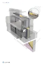
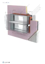
Page 8: ...8 70 FDS EX Product parts ...

Page 9: ...m H0 EX H2 EX P4 Actuator operated activation mechanism SET EX SRT EX P5 Inspection lid P6 Thermoelectric fuse ExPro TT 72 Schischek P8 Bendable hanger P9 Release and test button P10 Crank P11 Open position P12 Closed position P13 Hexagonal bent wrench No 10 not part of delivery ...

Page 10: ...ature and load bearing capacity Durability of operational reliability Pass open and closing cycle Assessed Performance FDS EI90S FDS EI120S 19 CE 1396 Systemair Production a s Hlavná 371 900 43 Kalinkovo Slovakia 1396 CPR 0169 FDS EI90S FDS EI120S valid for subgroups EX EN 15650 2010 Rectangular fire dampers Nominal activation conditions sensitivity Pass sensing element load bearing capacity sensi...

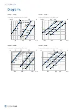
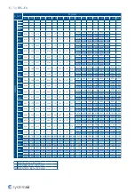
Page 11: ... A 45 dB A 50 dB A 25 dB A 30 dB A 35 dB A 40 dB A 45 dB A 50 dB A 25 dB A 30 dB A 35 dB A 40 dB A 45 dB A 50 dB A FDS 3G H0 EX Pressure drop sound power level A weighted 1000 2000 5000 m h 300 500 1000 l s 5 Pa Width 600 Height 100 Width 600 Height 200 Width 600 Height 300 25 dB A 30 dB A 35 dB A 40 dB A 45 dB A 50 dB A 25 dB A 30 dB A 35 dB A 40 dB A 45 dB A 50 dB A 55 dB A 25 dB A 30 dB A 35 dB...

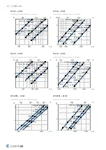
Page 12: ...5 dB A 40 dB A 45 dB A 50 dB A 25 dB A 30 dB A 35 dB A 40 dB A 45 dB A 50 dB A 55 dB A 25 dB A 30 dB A 35 dB A 40 dB A 45 dB A 50 dB A FDS 3G H0 EX Pressure drop sound power level A weighted 10000 20000 30000 m h 3000 5000 10000 l s 1 2 5 Pa Width 1200 Height 500 Width 1200 Height 600 Width 1200 Height 800 25 dB A 30 dB A 35 dB A 40 dB A 45 dB A 50 dB A 25 dB A 30 dB A 35 dB A 40 dB A 45 dB A 50 d...

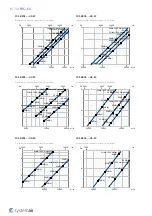
Page 13: ...Width 1400 Height 300 Width 1400 Height 400 25 dB A 30 dB A 35 dB A 40 dB A 45 dB A 50 dB A 25 dB A 30 dB A 35 dB A 40 dB A 45 dB A 50 dB A 55 dB A 25 dB A 30 dB A 35 dB A 40 dB A 45 dB A 50 dB A FDS EI90S H0 EX Pressure drop sound power level A weighted 20000 30000 50000 m h 5000 8000 10000 l s 1 2 5 Pa Width 1400 Height 700 Width 1400 Height 900 Width 1400 Height 1000 30 dB A 35 dB A 40 dB A 45 ...

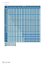
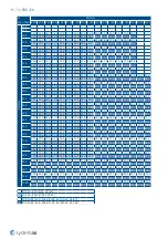
Page 14: ...245 0 260 0 277 450 0 094 0 114 0 120 0 134 0 136 0 154 0 175 0 195 0 215 0 219 0 235 0 248 0 256 0 276 0 280 0 296 0 316 500 0 105 0 128 0 135 0 151 0 153 0 174 0 196 0 219 0 242 0 246 0 265 0 278 0 287 0 310 0 315 0 333 0 356 550 0 142 0 15 0 167 0 170 0 193 0 218 0 243 0 268 0 273 0 294 0 309 0 319 0 344 0 349 0 369 0 395 560 0 145 0 153 0 171 0 173 0 197 0 222 0 248 0 274 0 279 0 300 0 315 0 3...

Page 15: ...0 570 0 586 0 612 0 692 0 719 0 747 0 775 0 803 0 831 0 858 0 886 0 678 0 706 0 733 0 761 0 788 0 816 0 843 0 87 630 0 451 0 479 0 507 0 535 0 563 0 591 0 602 0 619 0 647 0 729 0 758 0 788 0 817 0 846 0 875 0 905 0 934 0 715 0 744 0 773 0 802 0 831 0 86 0 889 0 918 650 0 467 0 496 0 525 0 554 0 583 0 612 0 624 0 641 0 670 0 754 0 784 0 815 0 845 0 875 0 905 0 936 0 966 0 74 0 77 0 8 0 83 0 86 0 89...

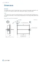
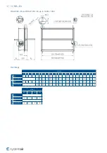
Page 16: ...R2 are the overhang of the fully open blade including seals and gaskets on the damper blade NOTES For a nominal size W 100 mm the internal width dimension is 100 mm the flange outside width dimension 152 mm and or for a nominal size H 100 mm the internal height dimension is 100 mm flange outside height dimension 152 mm FDS 3G EX 100 x 100 up to 1200 x 800 ...

Page 17: ...143 118 93 85 68 65 43 18 7 32 37 57 72 82 107 112 132 157 EI90S EI120S 160 145 110 102 85 82 60 35 10 15 20 40 55 65 90 95 115 140 R 2 mm 3G 43 18 5 3 2 27 52 60 77 80 102 127 152 177 182 202 217 227 252 257 277 302 EI90S EI120S 20 5 30 37 55 57 80 105 130 155 160 180 195 205 230 235 255 280 H mm 850 900 950 1000 R 1 mm 3G EI90S EI120S 165 190 215 240 R 2 mm 3G EI90S EI120S 305 330 355 380 ...

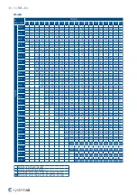
Page 18: ...9 1 19 3 20 0 20 6 21 0 21 9 22 1 22 8 23 7 500 10 7 11 7 12 0 12 7 12 8 13 7 14 7 15 7 16 7 16 9 17 7 18 2 18 6 19 6 19 8 20 6 21 6 14 2 15 2 15 5 16 2 16 3 17 2 18 2 19 2 20 2 20 4 21 2 21 7 22 1 23 1 23 3 24 1 25 1 550 12 4 12 7 13 5 13 6 14 5 15 6 16 7 17 7 17 9 18 8 19 4 19 8 20 9 21 1 21 9 22 9 15 9 16 2 17 0 17 1 18 0 19 1 20 2 21 2 21 4 22 3 22 9 23 3 24 4 24 6 25 4 26 4 560 12 6 12 9 13 6...

Page 19: ...7 60 5 65 7 70 9 70 1 71 5 72 8 600 32 6 35 6 37 1 39 2 40 7 41 3 42 2 42 2 43 7 56 8 57 3 57 7 63 9 69 0 69 8 70 7 71 6 36 1 39 1 40 6 42 7 44 2 44 8 45 7 45 7 47 2 60 3 60 8 61 2 67 4 72 5 73 3 74 2 75 1 630 33 9 37 0 38 6 40 7 42 2 42 8 43 8 43 8 45 3 66 0 67 4 68 5 69 6 70 5 71 0 72 1 73 1 37 4 40 5 42 1 44 2 45 7 46 3 47 3 47 3 48 8 69 5 70 9 72 0 73 1 74 0 74 5 75 6 76 6 650 34 7 37 9 39 5 4...

Page 20: ... AC DC Schischek ExMax SRT EX 24 240 V AC DC Schischek RedMax Example of the Atex Rectangular Fire Dampers Ordering Code FDS 3G EX FDS 3G 1200x800 H2 EX Atex rectangular fire damper nominal dimensions width height 1200 800 mm with open and closed position indication with 24 230 V contact microswitches Note The fire resistivity depends on the installation method FDS EI90S EX FDS EI120S EX FDS EI120...

Page 21: ...n opening must be added to the connecting duct W and H 200 Standardly in position BR and TR On demand in positions TL BL H 250 Standardly in position BR TR On demand in position TL LB BL W 800 Standardly in position BR TR On demand in position TL LB RB BL NOTES An inspection lid cannot be placed on position BR and BL on one damper An inspection lid cannot be placed on position TL and TR on one dam...

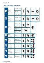
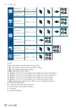
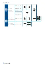
Page 22: ... 90 ho i o S EI 120 ho i o S 2 Dry FDS 3G EX 100 100 1200 800 EI 60 ve ho i o S a b c 360 EI 90 ve ho i o S 3H Hilti FDS 3G EX 100 100 1200 800 EI 60 ve i o S a b 360 5 1 On Out FDS 3G EX 100 100 1200 800 EI 60 ve i o S a b EI 90 ve i o S 5 2 On Out FDS 3G EX 100 100 1200 800 EI 60 ve i o S a b 5 3 On Out FDS 3G EX 100 100 1200 800 EI 60 ve i o S a b EI 90 ve i o S 5 4 On Out FDS 3G EX 100 100 120...

Page 23: ... boards and mineral wool filing 3 Soft Soft installation using mineral wool filing 3H Hilti Filling made only from Hilti foam 5 1 On Out ON OUT of the wall installation rated for EI90S Using 2 layers of Mineral Wool 5 2 On Out ON OUT of the wall installation rated for EI60S Using 1 layer of Mineral Wool 5 3 On Out ON OUT of the wall installation rated for EI90S Using Promatect boards 5 4 On Out ON...

Page 24: ...y part of the surrounding construction or wall which could cause damage and resulting damper failure It is recommended to connect the damper to a dilatation compensator on either end of the damper The damper driving mechanism can be placed on either side of the wall however it needs to be placed so as to ensure easy access during inspection According to standard EN 1366 2 the distance between the ...

Page 25: ...ext steps 5 After the filling hardens remove the duct support from inside of the damper 6 If needed uncover and clean the damper after installation 7 Check the damper s functionality Installation Standard Distances According to the standard EN 1366 2 the minimum distance from the wall or ceiling to the damper body is 75 mm For multiple crossings through a fire resistive wall the minimum distance b...

Page 26: ...26 70 FDS EX 1 Wet FDS EI90S EX W 1600 H 1000 EI 90 ve ho i o S a b c 1000 1000 FDS EI120S EX W 1600 H 1000 EI 120 ve ho i o S ...

Page 27: ...27 70 FDS EX ...

Page 28: ...ood beam wall 5a Vertical spruce wooden beam 60 100 mm 5b Horizontal spruce wooden beam 80 100 mm 6 Alternative thinner wall classified in accordance with EN 13501 2 2007 A1 2009 for the fire resistance required for product application 7 Area of 200 mm from opening around the damper must have the same composition and be created the same way as a flexible plasterboard wall Notes a Flexible plasterb...

Page 29: ... damper and the mounting opening for a circular damper use CBR FD cover boards for a rectangular damper use CBS FD cover boards with screws F1 through pre drilled holes 5 All the gaps between the cover boards between cover boards and the wall and between cover boards and the fire damper need to be filled with fire resistive coating F4 6 If needed uncover and clean the damper after installation 7 C...

Page 30: ...30 70 FDS EX ...

Page 31: ...31 70 FDS EX ...

Page 32: ...tal CW profiles 4d Mineral wool thickness cubic density see picture 5 Flexible wood beam wall 5a Vertical spruce wooden beam 60 100 mm 5b Horizontal spruce wooden beam 80 100 mm 6 Alternative thinner wall classified in accordance with EN 13501 2 2007 A1 2009 for the fire resistance required for product application 7 Area of 200 mm from opening around the damper must have the same composition and b...

Page 33: ... mechanism is located inspection openings and manufacturer labels 5 It is necessary to fix the dampers installed in a wall using four steel L profiles F7 from above and below Anchor the profiles to the wall on each end using at least one screw F1 and self drilling screws F8 against the damper with gaps of a maximum of 200 mm 6 Dampers installed into a ceiling need to be fixed onto the ceiling usin...

Page 34: ...EX 100 100 1200 800 EI 60 ve i o S a b 360 EI 90 ve i o S EI 60 ho i o S c EI 90 ho i o S EI 120 ho i o S 3 Soft FDS EI90S EX W 1600 H 1000 EI 90 ve ho i o S a b c 1000 1000 FDS EI120S EX W 1600 H 1000 EI 120 ho i o S c 1000 1000 ...

Page 35: ...35 70 FDS EX ...

Page 36: ...36 70 FDS EX ...

Page 37: ...rofiles 4c Horizontal CW profiles 4d Mineral wool thickness cubic density see picture 5 Flexible wood beam wall 5a Vertical spruce wooden beam 60 100 mm 5b Horizontal spruce wooden beam 80 100 mm 6 Alternative thinner wall classified in accordance with EN 13501 2 2007 A1 2009 for the fire resistance required for product application 7 Area of 200 mm from opening around the damper must have the same...

Page 38: ... partly flexible you can cut the excess foam that stands out from the wall 5 If needed uncover and clean the damper after installation 6 Check the damper s functionality Installation Standard Distances According to standard EN 1366 2 the minimum distance from the wall or ceiling to the damper body is 75 mm For multiple crossings through a fire resistive wall the minimum distance between two damper...

Page 39: ...39 70 FDS EX ...

Page 40: ...40 70 FDS EX ...

Page 41: ...ss cubic density see picture 5 Flexible wood beam wall 5a Vertical spruce wooden beam 60 100 mm 5b Horizontal spruce wooden beam 80 100 mm 6 Alternative thinner wall classified in accordance with EN 13501 2 2007 A1 2009 for the fire resistance required for product application 7 Area of 200 mm from opening around the damper must have the same composition and be created the same way as a flexible pl...

Page 42: ...e resistive coating F10 5 Secure the insulation for FDS 3G onto the square duct in two 90 mm layers Using 90 mm 1st layer and 180 mm 2nd layer long welding pins 18 19 for FDS EI90S onto the square duct in two 100 mm layers Using 100 mm 1st layer and 200 mm 2nd layer long welding pins 18 19 6 Cover the insulation face and perimeter up to 150 mm from the insulation edge using galvanized sheet metal ...

Page 43: ...43 70 FDS EX 5 1 On Out FDS EI90S EX W 1600 H 1000 EI 90 ve i o S a b ...

Page 44: ...44 70 FDS EX ...

Page 45: ... 3 Concrete masonry brick cellular concrete wall or ceiling 4 Flexible plasterboard wall 4a 2 layers of plasterboard fireproof plate type F EN 520 4b Vertical CW profiles 4c Horizontal CW profiles 4d Mineral wool thickness cubic density see picture 17 Mineral wool segment ULTIMATE Protect Slab 4 0 Alu1 ISOVER min 66 kg m3 inner layer outer layer 18 Welding pin length 180 or 200 mm Top without weld...

Page 46: ...ing construction LE 7 The distance P is the distance from the blade axis to the damper flange The distance depends on the type of damper used 6 Rules for hanger placements LP and duct suspensions LS depend on the damper s distance from the supporting construction LE F2 Plaster mortar concrete filling can serve as replacement of filling F9 Using plaster mortar concrete for filling the coating F10 i...

Page 47: ...einforce the rectangular duct with stiffening rods 30 along the insulated duct The first cross is placed on the wall the others at distances of LS 4 Insulate the damper and duct parts between the damper and the wall Glue the insulation 29 in one 80 mm layer onto the wall around the duct by using a suitable fire resistive coating F10 Secure the insulation 29 using 80 mm long welding pins 27 The act...

Page 48: ...48 70 FDS EX ...

Page 49: ...49 70 FDS EX ...

Page 50: ...250 mm distance of the pin from the edge 80 mm 28 U profile MQ31 HILTI top and bottom 29 Mineral wool segment thickness 80 mm min 66 kg m3 ISOVER Ultimate U Protect Slab 4 0 Alu1 30 Stiffening rods horizontal for W 600 mm vertical for H 400 mm Notes a Flexible plasterboard wall b Concrete masonry cellular concrete rigid wall ve Vertical wall 5 Rules for hanger placements and duct suspensions depen...

Page 51: ...ion 4 Fit 4 boards F15 of 100 mm in width around the duct and secure them to the wall using suitable screws F1 fasten an L profile F14 to the wall and the duct on the damper side fasten 4 boards 32 by joining them together in corners by screws 5 Cover the IKOWS FD accessory A4 and the boards 32 along the entire length with 40 mm thick boards 31 apply fire resistive coating F13 to all joints and fi...

Page 52: ...52 70 FDS EX ...

Page 53: ...53 70 FDS EX ...

Page 54: ...or suitable wall plug and screw size 6 F12 Mineral wool segment thickness of 50 mm min 150 kg m3 in a wall F13 Fire resistive coating Promat kleber K84 Promat F14 Steel L profile 25 25 2 mm F15 Gypsum board thickness of 15 mm width min 100 mm ...

Page 55: ...file 60 40 1 mm 42 Calcium silicate board thickness 40 60 mm Promatect L500 Promat 43 Screw with coak span max 250 mm 44 Corner connector MQP 1 HILTI Notes a Flexible plasterboard wall b Concrete masonry cellular concrete rigid wall ve Vertical wall 5 Rules for hanger placements and duct suspensions depend on the damper s distance from the supporting construction LE 6 Rules for hanger placements L...

Page 56: ...he IKOWS FD accessory A4 Cover the IKOWS FD accessory A4 and the boards 35 along the entire length with 20 mm thick boards 36 apply fire resistive coating F13 to all joints and fix the boards with screws 33 6 Bind the damper in the blade location using a profile 34 at the top and bottom damper side using threaded rods 20 and nuts The threaded rods are to be at a distance of a max of 50 mm from the...

Page 57: ...57 70 FDS EX 5 4 On Out FDS 3G EX 100 100 1200 800 EI 60 ve i o S a b ...

Page 58: ...58 70 FDS EX ...

Page 59: ...59 70 FDS EX ...

Page 60: ...s cubic density see picture 20 Steel threaded rod M10 32 Calcium silicate board thickness 40 20 20 100 mm Promatect L500 Promat 33 Screw 5 80 DIN7997 34 U profile MQ41 HILTI 35 Calcium silicate board thickness of 20 mm width min 100 mm 2 layers Promatect L500 Promat 36 Calcium silicate board thickness of 20 mm Promatect L500 Promat 37 Mineral wool segment thickness of 40 mm min 45 kg m3 38 Duct W ...

Page 61: ...supporting construction LE 7 The distance P is the distance from the blade axis to the damper flange The distance depends on the type of damper used 8 The hanger must be placed a max of 50 mm from the edge of the IKOWS FD 9 LP The recommended length of the Promatect boards from the producer is 1250 mm the legally allowed hanger span is 1500 mm F2 Plaster mortar concrete filling can serve as replac...

Page 62: ...des with screws 8 across the entire flange contact surface The maximum allowed gap between the screws is 200 mm 8 On the top side of dampers FDS 1A and FDS 1B forming a dividing line of the future second row FDS 2A and FDS 2B apply fire resistive coating and place mineral wool with a thickness of 80 mm F5 Using sheet metal belt 45 create a backstop belt with a length of WL from one side of the ins...

Page 63: ...63 70 FDS EX 7 Multi FDS EI90S EX W 1600 H 1000 EI 90 ve i o S b ...

Page 64: ...max 13 DIN7504 F16 Console 150 40 3 mm with two 6 mm openings 1 Fire damper actuator side 3 Concrete masonry brick cellular concrete wall or ceiling 45 Sheet metal belt 80 0 9 mm Notes b Concrete masonry cellular concrete rigid wall ve Vertical wall F2 Plaster mortar concrete filling can serve as replacement of filling F12 Using plaster mortar concrete for filling the coating F13 for mineral wool ...

Page 65: ...ing to EN 60079 10 Fire damper must be grounded Wires connecting damper parts must not be removed Switch off the power supply before working on any electrical equipment Only qualified electricians are allowed to work on the electrical system Microswitch Power Supply AC 125 250 V or DC 12 24 VElectrical Parameters 3A NOTES Supply via safety isolation transformer Power consumption must be observed L...

Page 66: ... electrical system If you use this type of wiring the heater does not work in case of open contact Standard wiring spring return in 10 sec Additional wiring terminal 5 spring return in 3 sec Actuator power supply AC 230 V 50 60 Hz 24 V AC DC NOTES Actuator Schischek ExMax 15 BF ON OFF operation 1 wire Ex i circuit SB 7 0 Integrated aux switches max 24 V 3A 240 V 0 25 A min 5 V 10 mA switching at 5...

Page 67: ...ctrical system If you use this type of wiring the heater does not work in case of open contact Standard wiring spring return in 10 sec Additional wiring terminal 5 spring return in approx 3 sec Actuator power supply AC 230 V 50 60 Hz 24 V AC DC NOTES Actuator Schischek RedMax 15 BF ON OFF operation 1 wire Ex i circuit SB 7 0 Integrated aux switches max 24 V 3A 240 V 0 25 A min 5 V 10 mA switching ...

Page 68: ...witch on the thermoelectric fuse The fire damper must become fully open the arrow on the actuator axis must show the position 90 which is the operating position Smoke detector and spring return actuator operated activation mechanism 1 The fire damper must open automatically after the actuator circuit closes the arrow on the actuator axis must show the position 90 2 Press the control switch P9 on t...

Page 69: ...he damper s internal parts the inspection lid should be opened For small sizes there is the possibility of removing the mechanism to perform the inspection The removable mechanism always needs to be returned back into the damper with the damper blade being closed The damper s internal casing thermal fuse sealings foaming substance the damper blade condition and accuracy of its closure during its l...

Page 70: ...Systemair DESIGN 2021 04 27 Handbook_FDS_EX_en GB ...

Reviews: