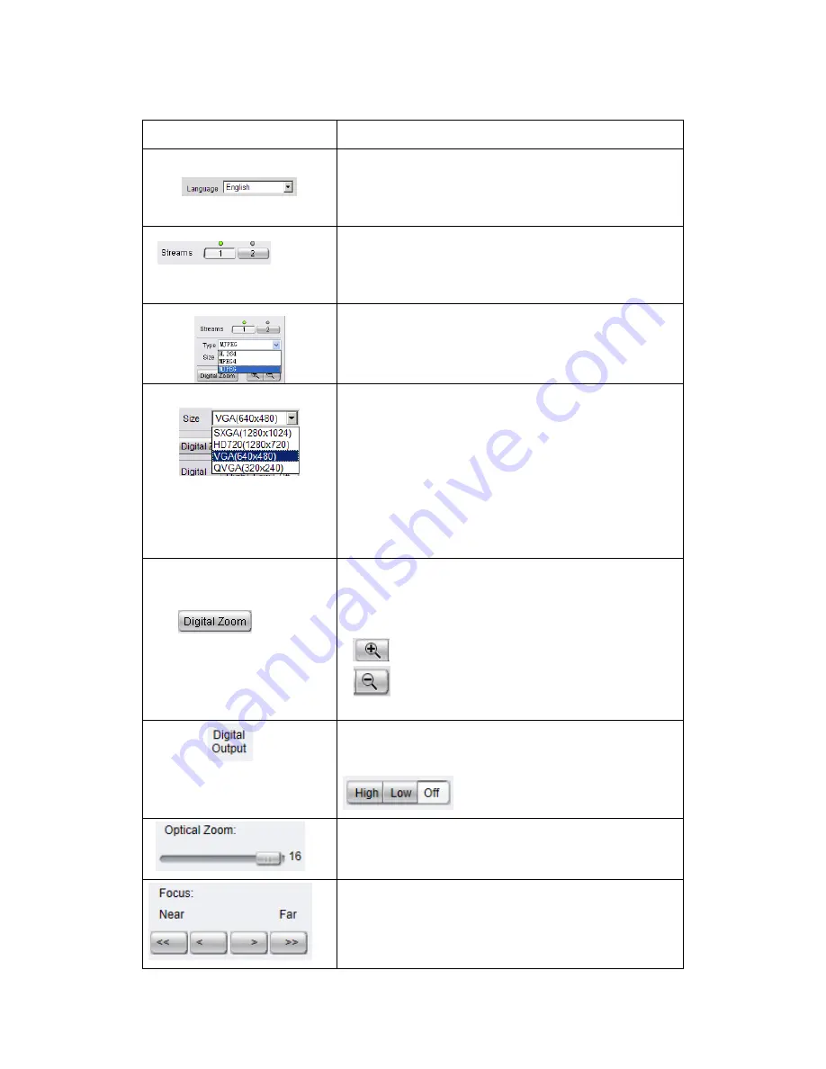
Surveon CAM1300 User Manual Download Page 35


35 


Control 

Description 


Language:

  Sets  the  UI  language.  Available 

languages  include  English,  Simplified  Chinese, 

and Traditional Chinese.


Streams: 

Allows  users  to  choose  which  camera 

stream  to  view.  The  indicator  above  the  stream 

will turn light green when the stream is selected.


Video  Format: 

Sets  the  compression  format  for 

the current stream. Available formats are H.264, 

MPEG4, and MJPEG.


Image  size  (resolution):

  Sets  the  resolution  of 

the  stream  currently  selected.  Options  are 

available  for  each  stream:  1080P  (1920  x  1080), 

SXGA  (1280  x  1024),  720P  (1280  x  720),  D1 

(720x480),  VGA  (640x480)  and  QVGA  (320x240) 

for  steam1;  640x360,  320x  180  and  192x108  for 

stream2.


Digital  Zoom: 

When  clicked,  activates  digital 

zoom  in  the  current  live-view  stream.  2  options 

are available when clicked: 

Zoom In  

Zoom Out  


To  set  the  digital  output  as  high  voltage  or 

ground or off can be done here. 


To  magnify  the  image,  change  its  focal  length 

to vary its view from 0 to 16. 


Change the depth of field by adjusting the Near 

and Far steps. 

Summary of Contents for CAM1300

Page 1: ...CAM13xx Series User Manual Release 1 2...

Page 2: ...fitness for any particular purpose Furthermore Surveon Technology reserves the right to revise this publication and to make changes from time to time in the content hereof without obligation to notif...

Page 3: ...3 Revision History Ver Version Description Date 1 0 Initial release January 2011 1 1 Built In MIC added for CAM1320 and UI Modified October 2013 1 2 Add new controller icons December 2013...

Page 4: ...CAM13xx Series 12 Chapter 2 Hardware Overview 14 2 1 Overview 14 Front View for1300 1301 14 Side View for CAM1320 14 Rear View for CAM1300 1301 15 Bottom View for CAM1320 15 2 2 Dimensions 16 CAM1300...

Page 5: ...Descriptions 34 4 2 Settings 37 General 37 Basic Settings 37 User Account 39 Date Time 42 Network 44 Network Configuration 44 Port Settings 46 UpnP 47 Wifi Setting 48 Video Audio Settings 50 Basic Se...

Page 6: ...Overview 76 5 2 Installing the IP Utility 76 5 3 IP Utility Basics 78 Starting the IP Utility 78 IP Utility Main Screen 78 Exiting the IP Utility 79 5 4 Camera Actions 80 Search 80 Login 81 Propertie...

Page 7: ...7 Copy to Group 99 5 6 Configuration Settings 101 Download Configuration 102 Update Configuration 103 5 7 Firmware Actions 104 Update Firmware 104 5 8 Focus Tool 106...

Page 8: ...alled according to specifications Provide a suitable power source with electrical overload protection Do not overload the AC supply branch circuit that provides power to the device ESD Precautions Ple...

Page 9: ...Ns they provide a complete budget conscious remote surveillance solution that are ultra clear and highly integrated CAM13xx series combine a user friendly interface and simplified installation with a...

Page 10: ...urveillance applications It is important to be able to clearly capture an incident in progress and identify persons or objects involved A network camera gives exceptional video quality even greater th...

Page 11: ...as in the market When a camera is manipulated in any way e g accidental redirection blocking defocusing spray painted covered or damaged it can automatically trigger recording and alert notifications...

Page 12: ...ns 4 2 mm F1 8 Default SNR 48dB WDR Yes Day Night ICR N A Yes N A IR LED N A Yes 10M N A Min Illumination 0 03 Lux F1 8 B W 0 3 Lux F1 8 Color 0 Lux IR LEDs on 0 3 Lux F1 8 Color 0 03 Lux F1 8 B W 0 3...

Page 13: ...ent Action Send snapshot or video clip by FTP or email record to NAS trigger DO Supported Protocols IPv4 ARP TCP UDP ICMP DHCP NTP DDNS SMTP FTP HTTP CIFS PPPoE UPnP RTP RTSP RTCP 3GPP Ethernet 10 100...

Page 14: ...14 Chapter 2 Hardware Overview 2 1 Overview Front View for1300 1301 CAM1300 CAM1301 Side View for CAM1320...

Page 15: ...15 Rear View for CAM1300 1301 Bottom View for CAM1320 1 1 Audio In Out 2 Status LED Indicator 3 Reset Button 4 USB Connector 5 Network Connector 6 Power Connector 7 IR LED 8 Screw Hole 9 Microphone...

Page 16: ...16 2 2 Dimensions CAM1300 1301 Unit mm inches...

Page 17: ...17 CAM1320 Unit mm inches...

Page 18: ...ystem or an active speaker with a built in amplifier A pair of headphones can also be attached Note CAM1320 does not support Audio In Out functions 2 Status LED indicator The LED will light up after t...

Page 19: ...actory Default Settings Note Camera resets can also be performed under System Reset To Factory Default on the web interface 4 USB Connector The USB Connector can be connected to a wireless USB adapter...

Page 20: ...he lock ring to adjust the desired angle of the camera 3 Retighten the lock ring after the desired angle is achieved 4 Connect the power cord to the power port 5 Insert the LAN cable to the LAN port 6...

Page 21: ...to mark the desired camera position on the ceiling Then use the anchor blots as a guide and cut a hole for wiring purposes if necessary Align the base plate with the anchor blots and fasten screws to...

Page 22: ...22 3 Connect the camera to network with the network connector 1 Internet Internet 4 Connect the power connector to a power outlet...

Page 23: ...boot up sequence has started Wait until the LED is in a steady green state indicating the camera boot up is complete 6 Loosen the screws on the front holder and adjust the direction of the lens 7 Loc...

Page 24: ...300 1301 Speaker Internet NAS FTP Email server Router Router Client Client Amplifier enabled Microphone CAM1320 1 Internet NAS FTP Email server Router Router Client Client Internet NAS FTP Email serve...

Page 25: ...25 2 6 Before You Start Please prepare a PC with Windows XP or above and web browsers installed...

Page 26: ...interface Internet Explorer is the recommended web browser for use with network cameras and our examples will be from this browser Usage on other browsers will be similar RTSP Player These include com...

Page 27: ...The details of the camera will display after the search is finished Note 1 The search may take up to 2 minutes depending on your network configuration 2 If your network does not have DHCP service the...

Page 28: ...prompted to install ActiveX components when accessing the network camera s Live View page click Yes when prompted You will be able to access the camera after installation is completed Under Windows t...

Page 29: ...of the System Logging off of the camera can be performed by closing the browser window Users can also choose to click the Logout link located at the top of the screen Using the Help Interface While us...

Page 30: ...layer and QuickTime Player are supported We will use Real Player as an example in this section 1 Launch Real Player 2 Select File Open URL to open a URL dialog box 3 Enter the camera URL in the addres...

Page 31: ...Set IP Only Port Settings V X UpnP V X Wifi Setting CAM1300 1311 Only V X Video Audio Settings Basic Settings V X Image Appearance Settings V X Video Streams V X Audio Settings V X PTZ RS 485 Setting...

Page 32: ...32 Export Import V X Reboot V V Camera Search X V Login V V Properties X V Delete from Tool X V Clearing and Setting Status X V Camera Group Actions X V Configuration Settings X V Focus Tool X V...

Page 33: ...nd pull up the help menu 2 Live View Controls These controls allow users to configure the live view streams and camera live view functionality 3 Button Bar These controls allow the user to quickly acc...

Page 34: ...Camera Name can be changed under Settings General Basic Settings Manual Record When clicked records the current live video Stops recording when clicked again The location for storing the video can be...

Page 35: ...esolution Sets the resolution of the stream currently selected Options are available for each stream 1080P 1920 x 1080 SXGA 1280 x 1024 720P 1280 x 720 D1 720x480 VGA 640x480 and QVGA 320x240 for stea...

Page 36: ...36 Control Description AutoFocus can be achieved by pressing this button P IRIS level can be adjusted Manually or Automatically...

Page 37: ...default set to model name MAC address displays on the center of the main page Users may replace the default name with a new name consisting of alphanumeric characters spaces and the character Camera N...

Page 38: ...era access o LED on during camera access LED default off flashing during camera access o LED off during camera access LED default on off during camera access o LED always off LED always off Click OK t...

Page 39: ...ity There are also two basic settings under user account settings Enable access without login Checking the checkbox will allow users to view the camera stream without having to login Maximum number of...

Page 40: ...name used to login to the system User Group The system allows for 2 types of users o Administrator Administrators have full access privileges o Operator Operators can only access the live view page P...

Page 41: ...control user access The password must be a combination of alphanumeric characters _ between 4 and 20 characters in length and must begin with an alphabet letter This password should be retyped in the...

Page 42: ...Time Settings There are 3 ways to set the system time Synchronize with NTP server NTP is a protocol for synchronizing the system clock to an external server If this option is chosen enter the IP addre...

Page 43: ...43 Day Light Saving Users can set the Day Light Saving Time by ticking on Enable Day Light Saving Click OK to save or Cancel to abort the changes before you leave the page...

Page 44: ...era They are found under Network Network Configuration Most of these settings vary with your specific hardware setup therefore the defaults are set for common SOHO level usage If you are using the cam...

Page 45: ...ect Enable PPPoE and fill in valid user name and password to connect the camera to the Internet DDNS Settings DDNS Dynamic Domain Name Server is a protocol that enables the camera to maintain a static...

Page 46: ...RTSP Settings and RTP Multicast Settings Note The default port numbers in this section are for the most part well known or commonly known values We recommend that they not be changed unless there is...

Page 47: ...rotocol The RTP Multicast video audio port and group address can also be set Click OK to save or Cancel to abort the changes before you leave the page UpnP Universal plug and play UPnP is a protocol t...

Page 48: ...l Panel Add or Remove Programs In the Add or Remove Programs page select Add Remove Windows Components Networking Services and click Details Select UPnP from the popup window and OK out to install UPn...

Page 49: ...in Password and Confirm Password Click OK to save or Cancel to abort the changes before you leave the page Note Only WEP Wireless Encryption Protocol is supported WAP Wireless Application Protocol WA...

Page 50: ...Basic Settings Video Orientation In certain mounting situations the default video output may not be oriented correctly This setting allows you to change the orientation of the output video Flip flips...

Page 51: ...and color All parameters are values ranging from 0 to 100 Dragging the slider to the right increases the value while dragging to the left lowers the value The adjustments will be displayed in real tim...

Page 52: ...meters can be changed D WDR Specifies if the wide dynamic range WDR function is activated If activated the WDR function will attempt to preserve detail at contrast extremes o D WDR Level Specifies the...

Page 53: ...White Balance This setting allows users to choose the color balancing method used o AWB Automatically chooses white level o MWB The user must specify the red and blue gain levels to achieve the corre...

Page 54: ...s when the camera will be in day mode To The time in hours and minutes when the camera will switch to night mode Chroma Suppress Reduces the false color phenomena Click OK to save or Cancel to abort t...

Page 55: ...stream o H 264 Provides the best compression and clear picture but is processor intensive o MJPEG Provides minimal compression with the best picture quality Each frame is stored as a discrete JPEG Thi...

Page 56: ...Video Quality Settings Sets the quality of the video image Constant Bit Rate In this mode the camera will maintain a constant bit rate output regardless of video quality Bit rates available are depend...

Page 57: ...io In Selects the source for the camera audio feed Line In an external source connected to the camera s line in port is the only option ADPCM Bit Rate Adaptive differential pulse code modulation ADPCM...

Page 58: ...uling The following parameters can be configured within this menu Manual Record To Defines the path for manual recording Screenshots and user recordings will be saved in this location Event Schedule R...

Page 59: ...and FTP notifications as well as remote recording Email Settings Email settings are used to configure e mail notifications Sender Email Address The return e mail address for notifications This should...

Page 60: ...1 User Name The user name of the FTP account Password The password of the FTP account FTP Folder Name The name of the folder on the FTP site which video files will be stored in NAS Settings NAS settin...

Page 61: ...ber of the window After creating the window clicking it will select the window You can drag and resize the window using your mouse You can also change the following parameters Window Name Tthe name of...

Page 62: ...ion Detection is active by checking the corresponding boxes and fill in a start time and end time for motion detection in the From and To boxes Click OK to save or Cancel to abort the changes before y...

Page 63: ...vents such as motion detection or DI triggers Schedule List Contains time based rules Each rule has an action list When the conditions for rule are met the actions specified by the rule are carried ou...

Page 64: ...filled in Name Specifies the name of the Event Minimum time interval between triggers The time frame in which a subsequent trigger of the same event will be ignored maximum 23 59 59 Enable Triggering...

Page 65: ...fer to the section on Motion Detection for details On Boot Trigger when camera reboots Video Loss Tampering Detection Trigger when video signal is lost or tampering is detected Please refer to the sec...

Page 66: ...the Event Server settings when triggered The video clip stored on both remote storage server and local storage is a video file 35 seconds in length 5 seconds before and 30 seconds after the trigger T...

Page 67: ...od select the days of the week that the trigger is active by checking the corresponding boxes and fill in a start time and end time for motion detection in the From and To boxes Never The event is nev...

Page 68: ...es are sent as attachments Record Records video to the server specified in the Event Server settings and the microSD card when triggered The video clip stored on both remote storage server and local s...

Page 69: ...be found under System System Status This section displays useful system information including Network Configuration defined manually or obtained from DHCP o IP Address o MAC Address o Subnet Mask o De...

Page 70: ...a settings both successful and unsuccessful triggered events and error messages This information can be very useful in the event of a camera failure or unauthorized entry Clicking Email will send the...

Page 71: ...all settings back to factory defaults 5 Click Upgrade to start the upgrade Upon completion of firmware upgrade the camera will reboot you will be logged off 6 The LED will flash amber during the firm...

Page 72: ...ncluding the IP address to be reset To reset the unit without changing parameters disconnect and reconnect the power connector Camera resets can also be performed under System Reset To Factory Default...

Page 73: ...well as import configuration details The following options are available Restart Camera Resets the camera when Apply is clicked Export Configuration Export the camera s settings and configurations by...

Page 74: ...et IP Only Port Settings V X UpnP V X Wifi Setting CAM1300 1311 Only V X Video Audio Settings Basic Settings V X Image Appearance Settings V X Video Streams V X Audio Settings V X PTZ RS 485 Settings...

Page 75: ...75 Export Import V V Reboot V V Camera Search X V Login V V Properties X V Delete from Tool X V Clearing and Setting Status X V Camera Group Actions X V Focus Tool X V...

Page 76: ...mera Utility also provides tools to perform simple connectivity configuration firmware upgrades and reboot operations The utility is intended to simplify the configuration and management of multiple c...

Page 77: ...sh to install the application for the current user only Just me or all users on this computer Everyone 5 Click Next to continue The system will respond with a ready screen Click Next again The system...

Page 78: ...ubnet as the computer In some cases this may result in longer wait times IP Utility Main Screen The IP Utility main screen is divided into 3 sections 1 Camera Group Display displays group details 2 Ca...

Page 79: ...79 Exiting the IP Utility To exit the IP utility click the X button on the top right corner of the screen or choose File Exit from the menu bar...

Page 80: ...ras listed as well as locates any new cameras connected on the same subnet The search is performed every time the IP utility starts To perform search again Click the Auto Search button or click Camera...

Page 81: ...equire that proper login credentials are supplied To login to a camera 1 Right click the camera you wish to set Select Login from the popup the system responds with the Login window Alternatively clic...

Page 82: ...me and password 3 Click OK to set the username and password Note To perform further configuration please make sure that the User set here has administrator privileges The default Username Password for...

Page 83: ...rties of a camera can be viewed by following these steps 1 Select a camera by checking the box in the first column of its listing 2 Right click the camera and select Properties or select Camera Proper...

Page 84: ...84 The Camera Information popup will display with camera details...

Page 85: ...Select one or more cameras by checking the box in the first column of their listing 2 Right click the camera s which you want to delete from the tool and select Delete from Tool The camera will be rem...

Page 86: ...86 Select All In a group context right clicking a camera and selecting Select All will select all the cameras in the group...

Page 87: ...o this 1 Select a camera by checking the box in the first column of its listing 2 Click the Reboot button or select Camera Configuration Reboot from the menu bar The camera will reboot If further conf...

Page 88: ...1 Click the Set IP button 2 You can choose to obtain an IP address from DHCP or assign a fixed IP 3 Select one or more cameras by checking the box in the first column of their listing Click Select All...

Page 89: ...89 Click OK to save or Cancel to abort the changes before you leave the page...

Page 90: ...Link to Camera 1 Select a camera by checking the box in the first column of its listing 2 Double click the selected camera or select Camera Link to Camera in the menu bar The camera s live view webpag...

Page 91: ...ement page of the selected camera 1 Select a camera by checking the box in the first column of its listing 2 Right click the camera and select User Manager or click Camera User Manager in the menu bar...

Page 92: ...ngs There are two pre defined subsections All Devices contains all the cameras in the tool as well as predefined groups New Devices and Warnings Errors MyGroup contains only user defined groups Add Gr...

Page 93: ...2 In the New Group Name field type in a group name 3 Click OK to add the group The group will appear under MyGroup Note Camera group names can contain upper and lower case letters numerals and the _ s...

Page 94: ...wish to delete 2 Choose Delete Group to delete the group Alternatively click the group and choose Delete Group from the Group menu 3 The system will ask to confirm the deletion Click Yes to delete the...

Page 95: ...Rename Group 1 Expand MyGroup and right click the group you wish to rename 2 Choose Rename Group Alternatively click the group and choose Rename Group from the Group menu The Rename Group popup appea...

Page 96: ...96 3 Enter a new group name in the New Group Name field 4 Click OK to save your changes Note Camera group names can contain upper and lower case letters numerals and the _ symbol...

Page 97: ...rom the Camera Group window select a group under MyGroup 2 Select one or more cameras from the existing group by checking the box in the first column of their listing 3 Right click the camera and sele...

Page 98: ...98 4 In the Select Group pop up box select the destination group 5 Click OK to move the selected camera s to the group Note Cameras can not be moved from groups under All Devices...

Page 99: ...oup 1 From the Device Group window select a group 2 Select one or more cameras from the existing group by checking the box in the first column of their listing 3 Right click the camera s and select De...

Page 100: ...100 4 In the Select Group pop up box select the destination group 5 Click OK to copy the selected camera s to the group...

Page 101: ...d and updated by selecting Camera Configuration or the process can be automated by downloading the configuration from one camera using the Download Configuration function and then using the Update Con...

Page 102: ...ck the camera which you want to download from and select Configuration Download Configuration or select Camera Configuration Download Configuration from the menu bar The Download Configuration popup w...

Page 103: ...s which you want to update to and select Configuration Update Configuration or select Camera Configuration Update Configuration from the menu bar The Update Configuration popup will display 3 Click t...

Page 104: ...irmware Actions Update Firmware Once a new version of the camera firmware is obtained the firmware can be updated using the following steps Note You must be logged into the camera to update the camera...

Page 105: ...ight click the camera s which you want to update to and select Maintenance Update Firmware or select Camera Maintenance Update Firmware from the menu bar The Update Firmware popup will display 3 Click...

Page 106: ...Focus Tool button to open it Information of Best Focus Value Current Focus Value and Focus Percent will be shown at the bottom of the Focus Tool Window You can click Refresh to get a new data after fo...

Reviews: