


396
-
3815Y1 SureFire PumpRight for Raven RCM
54
Revised 12/04/2019
1.
Be sure the Pressure Sensor that is displayed on your screen is the same sensor that is plugged into your harness
for that product (Sensor 1 or Sensor 2).
2.
Make sure the pins where the harness screws on to the end of the sensor have not been bent.
3.
Be sure Pressure Sensor is set up and calibrated in the display. Unplug the pressure harness before doing this.
S
etup > Settings > Pressure Sensor Setup. Select the sensor you want. > Calibrate Pressure Sensor >
Voltage
-
based Calibration > 50 mv/PSI.
4.
There should be a green LED light on the end of the pressure sensor. This may be difficult to see in daylight. The
sensor needs 12 v. Check between pins B&C on the Pressure connector on the harness that connects to the
pressure sensor. If there is no voltage here, check the voltage between pins 1 & 2 on the 12
-
pin connector labeled
PUMP.
5.
Testing Pressure Sensor Harnessing:
If the pressure sensor is not reading, you can use a AA or AAA battery to
test the harnessing. Connect the (
-
) end of the battery to pin C and the (+) end to pin A of the pressure connector.
The 1.5 v should show up as 30 psi on the screen. You can check this at
Diagnostics > System Information >
Pressure Sensors
. (0 PSI should be 0.0v)
Pressure Sensor is not reading
Section Valve(s) will not move
1.
Go to
Diagnostics
> Tests > Control/Section Test
to investigate this issue. If system shuts off with Solution Pump
Dry warning, use the Calibrate PWM Limits Test.
2.
Start Section Test. Check and uncheck the boxes. With the box checked the valve should turn on. The valve should
be off with the box not checked.
3.
If none of the valves are working, or if half of the valves are working, it may be a Power (or Ground) issue. The odd
-
numbered sections have one power source, the even
-
numbered sections have another power source. (See harness
diagrams)
4.
If a valve does not open, switch the connector that is plugged into that valve with a con-
nector that is plugged into a working valve. Also, plug in the connector to the non
-
working
valve to a valve that is working.
5.
Check the harness connection to the non
-
working valve. It is a 3
-
Pin Weather Pack con-
nector. Check voltage pin A to Pin B. Must be 12 volts, if not, go back to the next harness
connection and check the voltage there. (See harness diagrams for pins)
6.
If voltage is present on pins A&B of 3 pin connection to valve, then check Pin C to Pin B. This should be 12 volts
when the valve is commanded on or open. This should be zero volts when valve is off or closed.
7.
If signal voltage is not present to open valve, use diagrams to check at the 14
-
pin connector, then the 47
-
pin for volt-
age on the proper pin for that section.
8.
If harnesses and voltages are good, but valve still will not open, remove the actuator from the valve and see if the
actuator will work when it is not connected to the valve. Use a wrench to turn the valve to be sure it is moving freely.
Be sure actuator and valve are oriented correctly when you put them back together.
9.
If constant voltage (Pins A&B) and switched voltage (Pins C&B) are present, inspect, repair or replace the valve.
Pin
Function
A
+ 12 V Constant
B
Ground
C
+ 12 V Signal
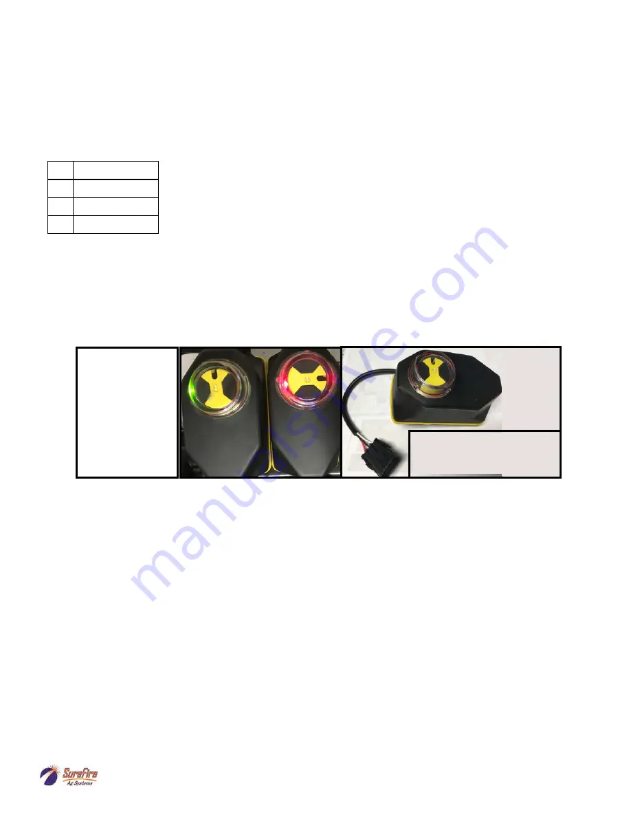
Green Light-
Valve ON
Red Light
Valve OFF–
connected to
Power
If valve indicator
stays GREEN all
the time or if valve
indicator is not in
full ON or full OFF
position, replace
actuator. Pull gray
pin to remove actu-
ator from valve.
Replacement Valve Actuator—
104
-
KZ1169
—KZ Electric
TX2 Series Actuator
This is a 3
-
way valve
. If product will not flow when valve is ON, either move the outlet hose to the other
outlet port, or remove actuator and rotate valve ball 180º, and replace actuator. Product should flow
through the port closest to the Indicator light when the valve is open (green).
SureFire
Ag
Systems