background image

Chapter 2: Installation

2-13

X8DTH

Rev. 2.0

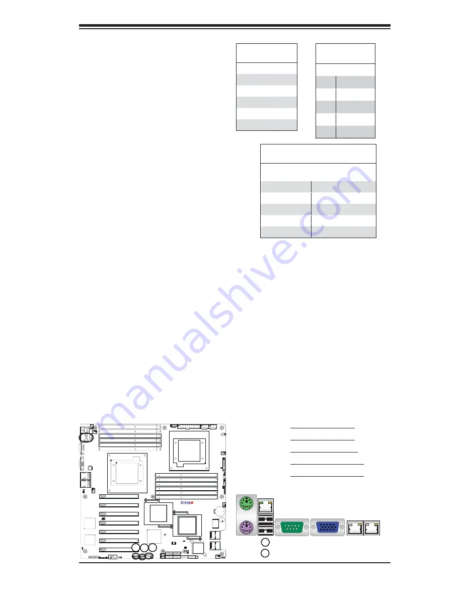
1. Backpanel USB 0

2. Backpanel USB 1

3. Front panel USB 3

4. Front panel USB 4/5

5. Front panel USB 6/7

Universal Serial Bus (USB)

Two Universal Serial Bus ports (USB 

0/1) are located on the I/O back panel. 

Additionally, five USB connections 

(USB 3, 4/5, 6/7) are on the mother-

board to provide front chassis access. 

(Cables are not included). See the 

tables on the right for pin defi nitions.

Back Panel USB

(USB 0/1)

Pin#     Defi nitions

1

+5V

2

PO-

3

PO+

4

Ground

5

N/A

Front Panel USB

Pin Defi nitions (USB 4/5, 6/7)

      USB4/6   
Pin #      Defi nition

      USB 5/7 
Pin #      Defi nition

1

+5V

1

+5V

2

PO-

2

PO-

3

PO+

3

PO+

4

Ground

4

Ground

5

Key

5

No connection

Front Panel USB

(USB 3) 

Pin#     Defi nition     

1

Vcc

2

Data-

3

Data+

4

Ground

5

NA

1

2

3

4

5

Summary of Contents for X8DTH-6

Page 1: ...USER S MANUAL Revision 1 0c X8DTH 6F X8DTH 6 X8DTH i X8DTH iF...

Page 2: ...RMICRO SHALL NOT HAVE LIABILITY FOR ANY HARDWARE SOFTWARE OR DATA STORED OR USED WITH THE PRODUCT INCLUDING THE COSTS OF REPAIRING REPLACING INTEGRATING INSTALLING OR RECOVERING SUCH HARDWARE SOFTWARE...

Page 3: ...ted processors This product is intended to be installed and serviced by professional technicians Manual Organization Chapter 1 describes the features specifications and performance of the mother board...

Page 4: ...iven to ensure proper system installation or to prevent damage to the components Note Additional Information given to differentiate various models or to ensure correct system setup X8DTH 6 X8DTH 6F X8...

Page 5: ...Micro Computer B V Het Sterrenbeeld 28 5215 ML s Hertogenbosch The Netherlands Tel 31 0 73 6400390 Fax 31 0 73 6416525 Email sales supermicro nl General Information support supermicro nl Technical Su...

Page 6: ...ng 2 1 2 2 Motherboard Installation 2 2 Tools Needed 2 2 Installation Instructions 2 2 2 3 Processor and Heatsink Installation 2 3 Installing a CPU Heatsink 2 5 2 4 Memory Installation 2 7 2 5 Control...

Page 7: ...e Disable 2 27 CMOS Clear 2 28 Watch Dog Enable Disable 2 28 I2 C Bus to PCI Exp Slots 2 29 VGA Enable 2 29 SAS Enable X8DTH 6 6F Only 2 30 2 8 Onboard LED Indicators 2 31 GLAN LEDs 2 31 IPMI Dedicate...

Page 8: ...Introduction 4 1 Starting BIOS Setup Utility 4 1 How To Change the Configuration Data 4 1 Starting the Setup Utility 4 2 4 2 Main Setup 4 2 4 3 Advanced Setup Configurations 4 4 4 4 Security Settings...

Page 9: ...tems have all been included with your motherboard If anything listed here is damaged or missing contact your retailer The following items are included in the retail box One 1 Supermicro Mainboard One...

Page 10: ...X8DTH i X8DTH iF Image Note The drawings and pictures shown in this manual were based on the latest PCB Revision available at the time of publishing of the manual The motherboard you ve received may...

Page 11: ...upermicro com sup port manuals X8DTH 6 X8DTH 6F X8DTH i X8DTH iF Layout SPI BIOS I SATA1 I SATA0 I SATA5 I SATA4 JBT1 SATA SGPIO0 DP5 LED5 DP4 JPL1 JPG1 JPB JPS1 JWD JI2C2 JI2C1 JOH1 JD1 LAN1 VGA FAN5...

Page 12: ...ing be sure to provide adequate air flow to the system Notes Quick Reference SPI BIOS I SATA1 I SATA0 I SATA5 I SATA4 JBT1 SATA SGPIO0 DP5 LED5 DP4 JPL1 JPG1 JPB JPS1 JWD JI2C2 JI2C1 JOH1 JD1 LAN1 VGA...

Page 13: ...Header JOH1 Overheat LED Header JPI2 C Power Supply SMBbus I2 C Header JPW1 JPW2 JPW3 24 pin ATX PWR 8 pin Secondary PWR See the Warning on Page 1 4 JWF1 SATA DOM Disk On Module Power Header JWOL1 Wak...

Page 14: ...7 BIOS 32 Mb AMI SPI Flash ROM PCI 2 2 ACPI 1 0 2 0 3 0 Plug and Play PnP DMI 2 3 USB Keyboard sup port and SMBIOS 2 3 PC Health Monitoring Onboard voltage monitors for CPU1 Vcore CPU2 Vcore CPU1 Vtt...

Page 15: ...rts and 5 Front Panel Accessible USB connections Super I O Winbond W83527HG LSI SAS2 2008 Controller supports eight SAS ports X8DTH 6 X8DTH 6F only Note 2 IPMI 2 0 with full KVM support X8DTH 6F iF on...

Page 16: ...LPC BUS 6 FRONT SPI WPCM450 U3H1 U25 PROCESSOR 2 PROCESSOR 1 ESI X4 800 1066 1333 DDR3 1 4 1 3 1 2 1 1 1 5 1 6 0 5 0 6 800 1066 1333 0 4 0 3 0 2 0 1 DDR3 6Gb s 0 1 2 3 4 5 6 7 Ports 7 8 PCI E X8 PCI E...

Page 17: ...eceiving in addition to a differential forwarded clock A full width QPI link pair provides 84 signals The Intel 5520 supports up to 36 PCI Express Gen2 lanes peer to peer read and write transactions T...

Page 18: ...is given or an error message is sent to the screen the user can adjust the voltage thresholds to define the sensitivity of the voltage monitor Fan Status Monitor with Firmware Control The PC health m...

Page 19: ...es while providing a processor architecture independent implementation that is compatible with both Windows 2000 and Windows 2003 Operating Systems Slow Blinking LED for Suspend State Indicator When t...

Page 20: ...o shield the computer from noise It is recommended that you also install a power surge protector to help avoid problems caused by power surges 1 7 Super I O The Super I O supports 360 K 720 K 1 2 M 1...

Page 21: ...USB 2 0 and 1 1 for remote keyboard mouse virtual media emulation It also provides LPC interface to control Super IO functions The Winbond WPCM450 BMC is connected to the network via an external Ethe...

Page 22: ...1 14 X8DTH 6 X8DTH 6F X8DTH i X8DTH iF User s Manual Notes...

Page 23: ...not touch its components peripheral chips memory modules or gold contacts When handling chips or modules avoid touching their pins Put the motherboard and peripherals back into their antistatic bags...

Page 24: ...the chassis 1 Locate the mounting holes on the moth 2 erboard Refer to the layout above for mounting hole locations Locate the matching mounting holes on 3 the chassis Align the mounting holes on the...

Page 25: ...nd heatsink fans When purchasing a motherboard without a 5500 Series processor pre 3 installed make sure that the CPU socket plastic cap is in place and none of the CPU socket pins are bent otherwise...

Page 26: ...U against the surface of the socket or its pins to avoid dam aging the CPU or the socket With the CPU inside the socket 4 inspect the four corners of the CPU to make sure that the CPU is properly inst...

Page 27: ...p plied Screw 1 Screw 2 Install Screw 1 Place the heatsink on top of the 2 CPU so that the four mounting holes are aligned with those on the retention mechanism 3 Install two diagonal screws ie the 1...

Page 28: ...loosen and 3 remove the heatsink screws from the motherboard in the se quence as show in the picture on the right Hold the heatsink as shown 4 in the picture on the right and gently wriggle the heats...

Page 29: ...odule vertically into its slot Pay attention to the notch 2 along the bottom of the module to prevent inserting the DIMM module incor rectly Gently press down on the DIMM module until it snaps into pl...

Page 30: ...DR3 ECC 1066 1333 SR DR 2 2 FBD DDR3 ECC 1066 SR DR QR UDIMM Unbuffered DIMM Population Table DIMM Slots per Channel DIMMs Populated per Channel DIMM Type Unb Unbuffered Speeds in MHz Ranks per DIMM M...

Page 31: ...dule This should release it from the slot 3 Release Tab Release Tab Possible System Memory Allocation Availability System Device Size Physical Memory Remaining Available 4 GB Total System Memory Firmw...

Page 32: ...pecification See the picture below for the colors and locations of the various I O ports 1 Back Panel Connectors IO Ports Back Panel I O Port Locations and Definitions Back Panel Connectors Keyboard P...

Page 33: ...erboard See the table at right for pin defini tions PS 2 Keyboard Mouse Pin Definitions PS2 Keyboard PS2 Mouse Pin Definition Pin Definition 1 KB Data 1 Mouse Data 2 No Connection 2 No Connection 3 Gr...

Page 34: ...ide serial connec tions to the motherboard See the table on the right for pin definitions Serial Ports Pin Definitions Pin Definition Pin Definition 1 DCD 6 DSR 2 RXD 7 RTS 3 TXD 8 CTS 4 DTR 9 RI 5 Gr...

Page 35: ...connections USB 3 4 5 6 7 are on the mother board to provide front chassis access Cables are not included See the tables on the right for pin definitions Back Panel USB USB 0 1 Pin Definitions 1 5V 2...

Page 36: ...he X8DTH iF 6F to provide KVM support for IPMI 2 0 All these ports accept RJ45 type cables Note Please refer to the LED Indicator Sec tion for LAN LED information LAN Ports Pin Definition Pin Definiti...

Page 37: ...ors are designed specifically for use with Supermicro server chassis See the figure below for the descriptions of the various control panel buttons and LED indicators Refer to the following section fo...

Page 38: ...connection is located on pins 15 and 16 of JF1 Refer to the table on the right for pin definitions NMI Button The non maskable interrupt button header is located on pins 19 and 20 of JF1 Refer to the...

Page 39: ...of JF1 and the LED connection for GLAN Port 2 is on Pins 9 and 10 Attach the NIC LED cables to display network activity Refer to the table on the right for pin definitions GLAN1 2 LED Pin Definitions...

Page 40: ...LED cable to the OH Fan Fail connections on pins 7 and 8 of JF1 to provide advanced warn ings for chassis overheat fan failure Refer to the table on the right for pin definitions OH Fan Fail LED Pin D...

Page 41: ...nds Refer to the table on the right for pin definitions Power Button Pin Definitions JF1 Pin Definition 1 Signal 2 3V Standby Reset Button The Reset Button connection is located on pins 3 and 4 of JF1...

Page 42: ...rsupplyconnector JPW1 and two 8 pin CPU PWR connectors JPW2 JPW3 on the motherboard These power connectors meet the SSI EPS 12V specifi cation In addition to the 24 pin ATX power connector the 12V 8 p...

Page 43: ...ID Key JL1 1 1 1 COM2 TPM JHB1 JWOL1 Wake On LAN JWF1 Chassis Intrusion A Chassis Intrusion header is located at JL1 on the motherboard Attach an appropriate cable from the chassis to inform you of a...

Page 44: ...ridge 5520 Intel IOH36D 2 5520 Intel RAID Key JL1 1 1 1 COM2 TPM JHB1 JWOL1 Wake On LAN JWF1 B A A PWR LED Speaker B WOL Power LED Speaker On the JD1 header pins 1 3 are used for power LED indication...

Page 45: ...2 5520 Intel RAID Key JL1 1 1 1 COM2 TPM JHB1 JWOL1 Wake On LAN JWF1 A B A OH Fan Fail LED B SATA SGPIO 0 C SATA SGPIO 1 SATA SGPIO 0 1 Headers Two SATA SGPIO General Pur pose Input Output headers SAT...

Page 46: ...4 7 Slot1 PCI E 2 0 X8 USB4 5 USB3 USB6 7 LSI SAS2008 FAN4 JPW3 P1 DIMM2B LAN CTRL SAS PHY I SATA2 I SATA3 X8DTH Rev 2 0 SATA SGPIO1 DP6 DP7 Intel South Bridge 5520 Intel IOH36D 2 5520 Intel RAID Key...

Page 47: ...DIMM3A FAN6 P2 DIMM3B JPI2C JPW1 JPW2 FAN1 P2 DIMM2A P2 DIMM2B P2 DIMM1A P2 DIMM1B FAN7 COM1 CPU1 JF1 CPU2 IPMI_LAN USB0 1 PWR_LED P1 DIMM1B P1 DIMM1A FAN2 P1 DIMM2A SMBus1 LAN2 FAN8 P1 DIMM3B Slot7 P...

Page 48: ...Slot5 PCI E 2 0 X8 Battery Slot4 PCI E 2 0 X8 Buzzer Slot3 PCI E 2 0 X8 FLASH IOH36D 1 BMC Slot2 PCI E 2 0 X8 SAS Activity SAS0 3 ICH10R SAS4 7 Slot1 PCI E 2 0 X8 USB4 5 USB3 USB6 7 LSI SAS2008 FAN4 J...

Page 49: ...DP7 Intel South Bridge 5520 Intel IOH36D 2 5520 Intel RAID Key JL1 1 1 1 COM2 TPM JHB1 JWOL1 Wake On LAN JWF1 2 7 Jumper Settings Explanation of Jumpers To modify the operation of the mother board ju...

Page 50: ...2 TPM JHB1 JWOL1 Wake On LAN JWF1 CMOS Clear JBT1 is used to clear CMOS Instead of pins this jumper consists of contact pads to prevent the accidental clearing of CMOS To clear CMOS use a metal object...

Page 51: ...TRL SAS PHY I SATA2 I SATA3 X8DTH Rev 2 0 SATA SGPIO1 DP6 DP7 Intel South Bridge 5520 Intel IOH36D 2 5520 Intel RAID Key JL1 1 1 1 COM2 TPM JHB1 JWOL1 Wake On LAN JWF1 A A JI2 C1 B JI2 C2 C VGA Enable...

Page 52: ...y Slot4 PCI E 2 0 X8 Buzzer Slot3 PCI E 2 0 X8 FLASH IOH36D 1 BMC Slot2 PCI E 2 0 X8 SAS Activity SAS0 3 ICH10R SAS4 7 Slot1 PCI E 2 0 X8 USB4 5 USB3 USB6 7 LSI SAS2008 FAN4 JPW3 P1 DIMM2B LAN CTRL SA...

Page 53: ...N LEDs Two LAN ports LAN 1 LAN 2 are located on the IO Backplane of the motherboard Each Ethernet LAN port has two LEDs The yellow LED indicates activity while the oth er Link LED may be green amber o...

Page 54: ...8 USB4 5 USB3 USB6 7 LSI SAS2008 FAN4 JPW3 P1 DIMM2B LAN CTRL SAS PHY I SATA2 I SATA3 X8DTH Rev 2 0 SATA SGPIO1 DP6 DP7 Intel South Bridge 5520 Intel IOH36D 2 5520 Intel RAID Key JL1 1 1 1 COM2 TPM JH...

Page 55: ...S Activity SAS0 3 ICH10R SAS4 7 Slot1 PCI E 2 0 X8 USB4 5 USB3 USB6 7 LSI SAS2008 FAN4 JPW3 P1 DIMM2B LAN CTRL SAS PHY I SATA2 I SATA3 X8DTH Rev 2 0 SATA SGPIO1 DP6 DP7 Intel South Bridge 5520 Intel I...

Page 56: ...X8 FLASH IOH36D 1 BMC Slot2 PCI E 2 0 X8 SAS Activity SAS0 3 ICH10R SAS4 7 Slot1 PCI E 2 0 X8 USB4 5 USB3 USB6 7 LSI SAS2008 FAN4 JPW3 P1 DIMM2B LAN CTRL SAS PHY I SATA2 I SATA3 X8DTH Rev 2 0 SATA SG...

Page 57: ...correct cable for each connector Refer to Page 1 1 for cables that came with your shipment A red mark on a wire indicates the location of pin 1 A F SATA0 5 G SATA0 3 X8DTH 6 6F H SATA4 7 X8DTH 6 6F SA...

Page 58: ...2 36 X8DTH 6 X8DTH 6F X8DTH i X8DTH iF User s Manual Notes...

Page 59: ...and 1 chassis Disconnect all ribbon wire cables from the motherboard including those for 2 the keyboard and mouse Remove all add on cards 3 Install CPU 1 first making sure it is fully seated and conn...

Page 60: ...emory_Beep_Code is issued by the system check the following Make sure that the DIMM modules are properly and fully installed 1 Check if different speeds of DIMMs have been installed and check if the B...

Page 61: ...hen 3 contacting Supermicro for technical support Motherboard model and PCB revision number BIOS release date version this can be seen on the initial display when your system first boots up System con...

Page 62: ...erboard back to our RMA Department for repair Note 2 For BIOS Recovery instructions please refer to the AMI BIOS Recovery Instruction Guide posted at http www supermicro com support manuals Question W...

Page 63: ...frame displays all the options that can be configured Grayed out options cannot be configured Options in blue can be configured by the user The right frame displays the key legend Above the key legen...

Page 64: ...ential damages arising from a BIOS update If you have to update the BIOS do not shut down or reset the system while the BIOS is updating This is to avoid possible boot failure 4 2 Main Setup When you...

Page 65: ...essor used in your system CPU Type This item displays the type of CPU used in the motherboard Speed This item displays the speed of the CPU detected by the BIOS Physical Count This item displays the n...

Page 66: ...s the bootup screen options to be modified between POST mes sages or the OEM logo Select Disabled to display the POST messages Select Enabled to display the OEM logo instead of the normal POST message...

Page 67: ...Override Restore on AC Power Loss Use this feature to set the power state after a power outage Select Power Off for the system power to remain off after a power loss Select Power On for the system pow...

Page 68: ...U If this item is set to Enabled the hardware prefetcher will prefetch streams of data and instructions from the main memory to the L2 cache in the forward or backward manner to improve CPU performanc...

Page 69: ...nnot thus preventing a worm or a virus from flooding illegal codes to overwhelm the processor or damage the system during an attack The default is Enabled Refer to Intel and Microsoft Web Sites for mo...

Page 70: ...re auto demote information The options are Disabled and Enabled ACPI T State Select Enabled to report Processor throttling in the ACPI The options are Disabled and Enabled Advanced Chipset Control CPU...

Page 71: ...ng A memory error correction scheme that allows the processor to write correct data back into the memory block from where it was read by the processor The options are Enabled and Disabled Patrol Scrub...

Page 72: ...eature reduces or increases the frequency the system prefetches data The options are 8 16 32 40 48 56 64 72 80 88 96 104 112 and 120 Intel VT d Select Enabled to enable Intel Virtualization Technology...

Page 73: ...port for operating systems that are not compatible with USB devices The options are Enabled and Disabled IDE SATA Configuration When this submenu is selected the AMI BIOS automatically detects the pre...

Page 74: ...pacities over 137 GB your system must be equipped with a 48 bit LBA mode addressing If not contact your manufacturer or install an ATA 133 IDE controller card that supports 48 bit LBA mode The options...

Page 75: ...gle Word DMA mode 2 It has a data transfer rate of 8 3 MB s Select MWDMA0 to allow the BIOS to use Multi Word DMA mode 0 It has a data transfer rate of 4 2 MB s Select MWDMA1 to allow the BIOS to use...

Page 76: ...VRAM This feature clears NVRAM Non Volatile Memory used for Flash ROM at bootup The options are No and Yes Plug Play OS Selecting Yes allows the OS to configure Plug Play devices This is not required...

Page 77: ...ial Port 1 and Serial Port 2 Select Disabled to prevent the serial port from accessing any system resources When this option is set to Disabled the serial port physically becomes unavailable Select 3F...

Page 78: ...tion active during POST and Boot Loader The options are Disabled Boot Loader and Always Terminal Type This feature allows the user to select the target terminal type for Console Redirec tion The optio...

Page 79: ...tems will be displayed for your reference only CPU 1 Temperature CPU 2 Temperature The CPU Temperature feature will display the CPU temperature status as detected by the BIOS Low This level is conside...

Page 80: ...r to Intel s Web site at www Intel com 2 To avoid possible overheating be sure to provide adequate airflow to the system System Temperature The system temperature will be displayed in degrees in Celsi...

Page 81: ...ported by the system The options are Enabled and Disabled Headless Mode This feature is used to enable system to function without a keyboard monitor and or mouse attached The options are Enabled and D...

Page 82: ...set to Yes the following items will display Indicate Physical Select Yes for a TPM device to be detected by the system at each system boot The options are Yes and No TPM Deactivated Select Set to acti...

Page 83: ...This section displays the BMC status codes View BMC System Event Log This feature displays the BMC System Event Log SEL It shows the total number of entries of BMC System Events To view an event press...

Page 84: ...a DHCP Dynamic Host Configuration Protocol server in the network that the system is attached to and request the next available IP address The options are DHCP and Static If Static is selected the fol...

Page 85: ...em powers down or resets after an operating system failure is detected The options are 5 Min 1 Min 30 Sec and 10 Sec Event Log Configuration View Event Log Use this option to view the System Event Log...

Page 86: ...eans that a user password has not been used Change Supervisor Password Select this feature and press Enter to access the submenu and then enter a new Supervisor Password User Access Level Available wh...

Page 87: ...w the system to check for a user or supervisor password at each system boot The options are Setup and Always Boot Sector Virus Protection When this item is enabled the AMI BIOS displays a warning when...

Page 88: ...able Removable Drives The settings are 1st boot device 2nd boot device and Disabled 1st Drive USB XXXXXXXXX 2nd Drive CD DVD Drives This feature allows the user to specify the boot sequence from avail...

Page 89: ...it from the Exit menu and press Enter Discard Changes Select this option and press Enter to discard all the changes and return to the AMI BIOS Utility Program Load Optimal Defaults To set this feature...

Page 90: ...4 28 X8DTH 6 X8DTH 6F X8DTH i X8DTH iF User s Manual Notes...

Page 91: ...system to continue with bootup If a fatal error occurs you should consult with your system manufacturer for pos sible repairs These fatal errors are usually communicated through a series of audible be...

Page 92: ...A 2 X8DTH 6 X8DTH 6F X8DTH i X8DTH iF User s Manual Notes...

Page 93: ...er diskette from booting into a Driver CD please set the SATA Configuration to Compatible Mode and configure SATA as IDE in the BIOS Setup After making the driver diskette be sure to change the SATA s...

Page 94: ...o Doctor III displays crucial system information such as CPU temperature system voltages and fan status See the Figure below for a display of the Supero Doctor III interface Note 1 The default user na...

Page 95: ...te Control Note SD III Software Revision 1 0 can be downloaded from our Web site at ftp ftp supermicro com utility Supero_Doctor_III You can also download SDIII User s Guide at http www supermicro com...

Page 96: ...B 4 X8DTH 6 X8DTH 6F X8DTH i X8DTH iF User s Manual Notes...

Page 97: ...expected to result in significant injury or loss of life or catastrophic property damage Accordingly Supermicro disclaims any and all liability and should buyer use or sell such products for use in su...

Reviews: