Chapter 5: Advanced Motherboard Setup
5-11
Processors and their Corresponding Memory
Modules
CPU#
Corresponding DIMM Modules
CPU 1
P1-DIMMA1
P1-DIMMB1
P1-DIMMC1
P1-DIMMD1
CPU2
P2-DIMME1
P2-DIMMF1
P2-DIMMG1
P2-DIMMH1
Processor and Memory Module Population
Number of
CPUs+DIMMs
CPU and Memory Population Confi guration Table
(*For memory to work proper, please install DIMMs in pairs)
1 CPU &
2 DIMMs
CPU1
P1-DIMMA1/P1-DIMMB1
1 CPU &
4 DIMMs
CPU1
P1-DIMMA1/P1-DIMMB1, P1-DIMMC1/P1-DIMMD1
2 CPUs &
4 DIMMs
CPU1 + CPU2
P1-DIMMA1/P1-DIMMB1, P2-DIMME1/P2-DIMMF1
2 CPUs &
6 DIMMs
CPU1 + CPU2
P1-DIMMA1/P1-DIMMB1, P2-DIMME1/P2-DIMMF1, P1-DIMMC1/P1-DIMMD1
2 CPUs &
8 DIMMs
CPU1/CPU
P1-DIMMA1/P1-DIMMB1, P2-DIMME1/P2-DIMMF1, P1-DIMMC1/P1-DIMMD1,
P2-DIMMG1/P2-DIMMH1
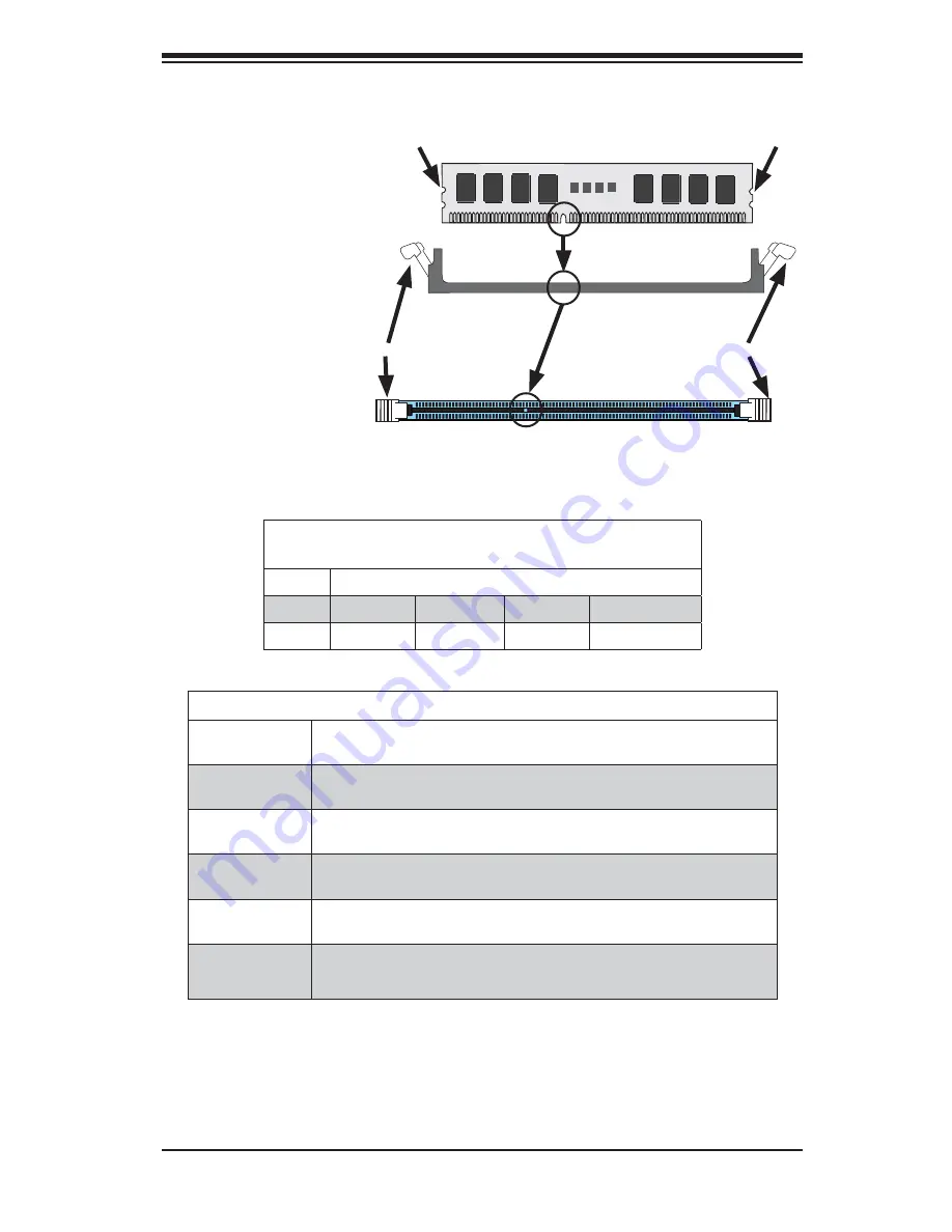
To I n s t a l l :
I n s e r t
module vertically and
press down until it
s n a p s i n t o p l a c e .
Pay attention to the
alignment notch at
the bottom.
To R e m o v e :
U s e
your thumbs to gently
push the release tabs
near both ends of the
module. This should
release it from the
slot.
Top View of DDR3 Slot
Release Tab
Release Tab
Note:
Notch should align with
the receptive key point on
the slot.
Notch
Notch
Front View
Figure 5-2. Installing DIMM into Slot
Summary of Contents for SUPERSERVER 6027TR-H71FRF
Page 1: ... SUPER USER S MANUAL Revision 1 0 SUPERSERVER 6027TR H71QRF 6027TR H71FRF 6027TR H71RF ...
Page 5: ...v SUPERSERVER 6027TR H71QRF H71FRF H71RF USER S MANUAL Notes ...
Page 10: ...x Notes SUPERSERVER 6027TR H71QRF H71FRF H71RF USER S MANUAL ...
Page 28: ...2 10 SUPERSERVER 6027TR H71QRF H71FRF H71RF USER S MANUAL Notes ...
Page 32: ...SUPERSERVER 6027TR H71QRF H71FRF H71RF USER S MANUAL 3 4 Notes ...
Page 66: ...5 6 SUPERSERVER 6027TR H71QRF H71FRF H71RF USER S MANUAL Notes ...
Page 73: ...Chapter 6 Advanced Chassis Setup 6 7 Figure 6 5 Replacing a System Fan in the Fan Housing ...
Page 114: ...A 2 SUPERSERVER 6027TR H71QRF H71FRF H71RF USER S MANUAL Notes ...


