background image

5-16

S

UPER

S

ERVER 6015B-UR/6015B-U/6015B-NTR/6015B-NT User's Manual

ATX PS/2 Keyboard and 
PS/2 Mouse Ports

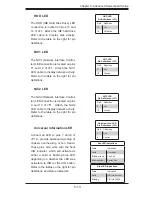
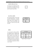
The ATX PS/2 keyboard and the PS/2 

mouse ports are located beside the 

USB ports.  See the table on the right 

for pin defi nitions.  

Power LED/Speaker  

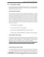
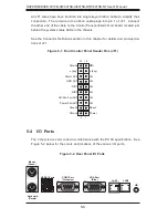
On the JD1 header, pins 1-3  are for 

a power LED, pins 4-7 are for the 

speaker.  See the table on the right 

for speaker pin defi nitions.   


Note

: The speaker connector pins are 

for use with an external speaker.  If 

you wish to use the onboard speaker, 

you should close pins 6-7 with a 

jumper.  

PS/2 Keyboard and 

Mouse Ports 

Pin Defi nitions

Pin#     Defi nition     

1

Data

2

NC

3

Ground

4

VCC

5

Clock

6

NC

Speaker Connector

 Pin Defi nitions (JD1)

Pin #      Function       Defi nition

4

+

Speaker data (red wire)

5

Key

No connection

6

Key

7

Speaker data

Overheat LED

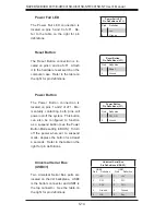
Connect an LED to the JOH1 header 

to provide warning of a chassis over-

heating condition.  See the table on the 

right for pin defi nitions.

Overheat LED 

Pin Defi nitions 

(JOH1)

Pin#     Defi nition     

1

+5V

2

OH Active

Chassis Intrusion 

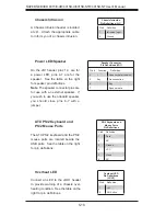
A Chassis Intrusion header is located 

at JL1.  Attach the appropriate cable 

to inform you of a chassis intrusion.   


Chassis Intrusion

Pin Defi nitions (JL1)

Pin#     Defi nition     

1

Intrusion Input

2

Ground

Summary of Contents for SUPERSERVER 6015B-NT

Page 1: ...SUPERSERVER 6015B UR SUPERSERVER 6015B U SUPERSERVER 6015B NTR SUPERSERVER 6015B NT USER S MANUAL 1 0b SUPER...

Page 2: ...FROM THE USE OR INABILITY TO USE THIS PRODUCT OR DOCUMENTATION EVEN IF ADVISED OF THE POSSIBILITY OF SUCH DAMAGES IN PARTICULAR SUPER MICRO SHALL NOT HAVE LIABILITY FOR ANY HARDWARE SOFTWARE OR DATA S...

Page 3: ...ter 1 Introduction The rst chapter provides a checklist of the main components included with the server system and describes the main features of the X7DBU serverboard and the SC815TQ R650U SC815TQ 56...

Page 4: ...efer to this chapter when adding or removing processors or main memory and when recon guring the serverboard Chapter 6 Advanced Chassis Setup Refer to Chapter 6 for detailed information on the SC815TQ...

Page 5: ...v Preface Notes...

Page 6: ...oosing a Setup Location 2 2 Rack Precautions 2 2 Server Precautions 2 2 Rack Mounting Considerations 2 3 2 4 Installing the System into a Rack 2 4 2 5 Checking the Serverboard Setup 2 8 2 6 Checking t...

Page 7: ...lling Memory 5 7 5 6 Adding PCI Cards 5 9 5 7 Serverboard Details 5 10 X7DBU Layout 5 10 X7DBU Quick Reference 5 11 5 8 Connector De nitions 5 12 ATX Power Connector 5 12 Auxiliary Power Connector 5 1...

Page 8: ...oppy IDE and SATA Drive Connections 5 22 Floppy Connector 5 22 IDE Connector 5 23 SATA Ports 5 23 Chapter 6 Advanced Chassis Setup 6 1 Static Sensitive Devices 6 1 6 2 Control Panel 6 2 6 3 System Fan...

Page 9: ...7 1 7 2 Running Setup 7 2 7 3 Main BIOS Setup 7 2 7 4 Advanced Setup 7 7 7 5 Security 7 23 7 6 Boot 7 24 7 7 Exit 7 25 Appendices Appendix A BIOS POST Messages Appendix B BIOS POST Codes Appendix C S...

Page 10: ...Notes x SUPERSERVER 6015B UR 6015B U 6015B NTR 6015B NT User s Manual...

Page 11: ...ating fans FAN 0086L One 1 IDE cable CBL 0139L Two 2 passive CPU heatsinks SNK P0017 Riser Cards see Section 5 6 for details One 1 RSC R1UU XR for PCI X card pre installed One 1 RSC R1UU E8R for PCI X...

Page 12: ...per settings UIO 6015B UR 6015B U The X7DBU is a specially designed serverboard that features Supermicro s UIO Universal I O technology UIO serverboards have a PCI Express x8 connector that can suppor...

Page 13: ...ly consisting of two power modules The system does not need to be shut down when replacing or removing a single power supply module The SC815TQ 560U features a single 560W power supply module The syst...

Page 14: ...to be used in a 1U rackmount con guration Ports on the I O backplane include one COM port a VGA port two USB 2 0 ports PS 2 mouse and keyboard ports and two gigabit Ethernet ports A UID Unit Identi er...

Page 15: ...ils 5000P ESB2 CPU 1 PCI E x8 slot Gb LAN Ports 2 SATA Ports 4 IDE USB Ports 5 S I O FWH Kybd Mouse FDD COM Ports CPU 2 FBD CH0 SXB1 PCI E x16 PCI X slot ATI ES1000 USB 2 0 LPC Bus DDR2 667 533 FBD DI...

Page 16: ...ro com Europe Address Super Micro Computer B V Het Sterrenbeeld 28 5215 ML s Hertogenbosch The Netherlands Tel 31 0 73 6400390 Fax 31 0 73 6416525 Email sales supermicro nl General Information support...

Page 17: ...maged in any way If the server itself shows damage you should le a damage claim with the carrier who delivered it Decide on a suitable location for the rack unit that will hold the 6015B UR 6015B U 60...

Page 18: ...tabilizers should be attached to the rack In multiple rack installations the racks should be coupled together Always make sure the rack is stable before extending a component from the rack You should...

Page 19: ...mised Mechanical Loading Equipment should be mounted into a rack so that a hazardous condition does not arise due to uneven mechanical loading Circuit Overloading Consideration should be given to the...

Page 20: ...ation instructions that came with the rack unit you are using Identifying the Sections of the Rack Rails You should have received two rack rail assemblies in the rack mounting kit Each assembly consis...

Page 21: ...bracket to the front side of the outer rail with two screws and the long bracket to the rear side of the outer rail with three screws Repeat these steps for the left outer rail Locking Tabs Both chass...

Page 22: ...erver into the rack Do this by lining up the rear of the chas sis rails with the front of the rack rails Slide the chassis rails into the rack rails keeping the pressure even on both sides you may hav...

Page 23: ...al First determine how far follow the server will extend out the front of the rack Larger chassis should be positioned to balance the weight between front and back If a bezel is included on your serve...

Page 24: ...the system from the rack completely depress the locking tabs in the chassis rails push the right side tab down and the left side tab up to continue to pull the system out past the locked position 2 C...

Page 25: ...Chapter 2 Server Installation 2 9 Figure 2 5 Accessing the Inside of the System...

Page 26: ...k drive to the system 3 Check the SATA disk drives Depending upon your system s con guration your system may have one or more drives already installed If you need to install SATA drives please refer t...

Page 27: ...rol Panel Buttons There are three push buttons located on the front of the chassis a reset button a UID button and a power on off button UID Depressing the UID unit identi er button illuminates an LED...

Page 28: ...w in the system or the ambient room temperature being too warm Check the routing of the cables and make sure all fans are present and operating normally You should also check to make sure that the cha...

Page 29: ...d when the system is operating 3 4 SATA Drive Carrier LEDs Each Serial ATA drive carrier has two LEDs Green When illuminated the green LED on the front of the SATA drive car rier indicates drive activ...

Page 30: ...3 4 SUPERSERVER 6015B UR 6015B U 6015B NTR 6015B NT User s Manual Notes...

Page 31: ...rst power down the system with the operating system and then unplug the power cords from all the power supply modules in the system When working around exposed electrical circuits another person who...

Page 32: ...oling fan Remove any jewelry or metal objects from your body which are excellent metal conductors that can create short circuits and harm you if they come into contact with printed circuit boards or a...

Page 33: ...se Touch a grounded metal object before removing any board from its antistatic bag Do not let components or PCBs come into contact with your clothing which may retain a charge even if you are wearing...

Page 34: ...is cover is in place when the 6015B UR 6015B U 6015B NTR 6015B NT is operating to ensure proper cooling Out of warranty damage to the 6015B UR 6015B U 6015B NTR 6015B NT system can occur if this pract...

Page 35: ...t the size and weight of the serverboard can cause it to bend if handled improperly which may result in damage To prevent the serverboard from bending keep one hand under the center of the board to su...

Page 36: ...atsinks and fans 2 When purchasing a Xeon 5300 5100 5000 CPU or when receiving a serverboard with a CPU pre installed make sure that the CPU plastic cap is in place and none of the CPU pins are bent o...

Page 37: ...or vertically and do not rub the CPU against any surface or any of the contacts which may damage the CPU and or contacts 7 With the CPU in the socket inspect the four corners of the CPU to make sure...

Page 38: ...on mechanism 3 Screw in two diagonal screws i e the 1 and the 2 screws until just snug Do not fully tighten the screws or you may damage the CPU 4 Add the two remaining screws then nish the installati...

Page 39: ...ons noted should be connected See the serverboard layout diagram in this chapter for connector locations DVD ROM Drive cable IDE 1 Control Panel cable JF1 see next page SATA cables 6015B NTR 6015B NT...

Page 40: ...d the system status LEDs in the chassis See the Connector De nitions section in this chapter for details and pin descrip tions of JF1 NMI x key Vcc Vcc Vcc Vcc Vcc Vcc Reset Power Ground x key Power L...

Page 41: ...e in the slot Repeat for all modules see step 1 above Memory Support The X7DBU supports up to 32 GB of ECC FBD Fully Buffered DIMM DDR2 667 or DDR2 533 SDRAM The memory is an interleaved con guration...

Page 42: ...sh memory System BIOS 1 MB 3 99 Local APIC 4 KB 3 99 Area Reserved for the chipset 2 MB 3 99 I O APIC 4 Kbytes 4 KB 3 99 PCI Enumeration Area 1 256 MB 3 76 PCI Express 256 MB 256 MB 3 51 PCI Enumerati...

Page 43: ...e installing a PCI add on card make sure you install it into the correct riser card Begin by releasing the locking tab that corresponds to the slot you wish to populate Insert the expansion card into...

Page 44: ...ry LAN1 LAN2 UIOP SXB2 SXB2 PCI E x8 SXB1 PCI E x16 DIMM 4B JPW3 JPW1 North Bridge 5000P DIMM 4A DIMM 3B DIMM 3A DIMM 2B DIMM 2A DIMM 1B DIMM 1A SATA0 SATA1 SATA2 SATA3 SATA4 SATA5 IDE 1 BIOS Floppy A...

Page 45: ...D1 Power LED pins1 3 Speaker Header pins 4 7 JF1 Front Control Panel Connector JL1 Chassis Intrusion Header JK1 Keylock Header JOH1 Overheat LED JPW1 Primary 20 Pin ATX Power Connector JPW2 Auxiliary...

Page 46: ...mary ATX power connector above the Auxiliary 4 pin connector at JPW2 must also be con nected to your power supply See the table on the right for pin de nitions NMI Button Pin De nitions JF1 Pin De nit...

Page 47: ...on pins 13 and 14 of JF1 Attach the IDE hard drive LED cable to display disk activity Refer to the table on the right for pin de nitions HDD LED Pin De nitions JF1 Pin De nition 13 Vcc 14 HD Active Un...

Page 48: ...press the button for at least 4 seconds Refer to the table on the right for pin de nitions Universal Serial Bus USB0 1 Two Universal Serial Bus ports are located on the I O backplane USB0 is the botto...

Page 49: ...he header but not on the port NC indicates no connection Serial Port Pin De nitions COM1 COM2 Pin De nition Pin De nition 1 DCD 6 DSR 2 RXD 7 RTS 3 TXD 8 CTS 4 DTR 9 RI 5 Ground 10 NC 4 pin Fan Header...

Page 50: ...er you should close pins 6 7 with a jumper PS 2 Keyboard and Mouse Ports Pin De nitions Pin De nition 1 Data 2 NC 3 Ground 4 VCC 5 Clock 6 NC Speaker Connector Pin De nitions JD1 Pin Function De nitio...

Page 51: ...ns You must have a WOR card and cable to use this feature SMB The System Management Bus header for the PCI bus is designated SMB Connect the appropriate cable here to utilize SMB on your system See th...

Page 52: ...e management functions Connect the appropriate cables from the backplane to the SGPIO1 and SGPIO2 headers to utilize SATA management functions on your system Alarm Reset JAR The system will notify you...

Page 53: ...ar CMOS and will also clear any passwords Instead of pins this jumper consists of contact pads to prevent accidentally clearing the contents of CMOS To clear CMOS 1 First power down the system and unp...

Page 54: ...he table on the right for jumper settings Watch Dog must also be en abled in BIOS Note When enabled the user needs to write their own application software to disable the Watch Dog Timer LAN Enable Dis...

Page 55: ...ted with the connection speed LED LAN LED Connection Speed Indicator LED Color De nition Off 10 MHz Green 100 MHz Amber 1 GHz LE1 The LE1 LED located near JD1 is the power LED LE1 illuminates when the...

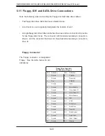
Page 56: ...nects to drive A and the connector that does not have twisted wires always connects to drive B Floppy Connector The oppy connector is designated Floppy See the table below for pin de nitions Floppy Dr...

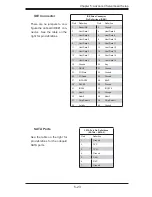
Page 57: ...0 Host Data 11 11 Host Data 3 12 Host Data 12 13 Host Data 2 14 Host Data 13 15 Host Data 1 16 Host Data 14 17 Host Data 0 18 Host Data 15 19 Ground 20 Key 21 DRQ3 22 Ground 23 I O Write 24 Ground 25...

Page 58: ...5 24 SUPERSERVER 6015B UR 6015B U 6015B NTR 6015B NT User s Manual Notes...

Page 59: ...To prevent damage to any printed circuit boards PCBs it is important to handle them very carefully The following measures are generally suf cient to protect your equipment from ESD damage Precautions...

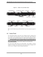
Page 60: ...n the Control Panel PCB printed circuit board Make sure the red wire plugs into pin 1 on both connectors Pull all excess cabling out of the air ow path The control panel LEDs inform you of system stat...

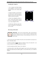
Page 61: ...ue to run with a failed fan Remove the top chassis cover while the system is still running to determine which of the two fans has failed Then power down the system before replacing a fan Removing the...

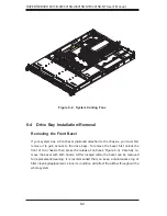
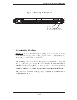
Page 62: ...you must rst remove it to gain access to the drive bays To remove the bezel rst unlock the front of the chassis then press the release knob see Figure 6 3 Carefully re move the bezel with both hands...

Page 63: ...ppy Disk Drives For installing removing a DVD ROM or oppy disk drive you will need to gain access to the inside of the 6015B UR 6015B U 6015B NTR 6015B NT by removing the top cover of the chassis Proc...

Page 64: ...new drive install a drive into the carrier with the printed circuit board side facing down so that the mounting holes align with those in the carrier Secure the drive to the carrier with six screws as...

Page 65: ...aning they can be removed and installed without powering down the system To remove a carrier push the release button located beside the drive LEDs Then swing the colored handle fully out and use it to...

Page 66: ...rom the chassis to gain full access to the inside of the server With the chassis cover removed unplug the power and data cables from the drive you want to remove Then locate the locking tab at the rea...

Page 67: ...eaning you can replace the failed module without powering down the system Removing Replacing the Power Supply You do not need to shut down the system to replace a power supply module The redundant fea...

Page 68: ...on the control panel off then unplug the power cord from the system Replace with the same model p n PWS 561 1H20 which can be ordered directly from Supermicro see Contact Information in the Preface To...

Page 69: ...Chapter 6 Advanced Chassis Setup 6 11 Figure 6 6 Removing Replacing the Power Supply...

Page 70: ...6 12 SUPERSERVER 6015B UR 6015B U 6015B NTR 6015B NT User s Manual Notes...

Page 71: ...pro vides power to the CMOS Logic enabling it to retain system parameters Each time the computer is powered on the computer is con gured with the values stored in the CMOS Logic by the system BIOS wh...

Page 72: ...two ways 1 By pressing Delete immediately after turning the system on or 2 When the message shown below appears brie y at the bottom of the screen during the POST Power On Self Test press the Delete...

Page 73: ...ate Using the arrow keys highlight the month day and year elds and enter the correct data Press the Enter key to save the data BIOS Date This eld displays the date when this version of BIOS was built...

Page 74: ...ems Set the correct con gurations accordingly The items included in the submenu are The following items will be displayed in the submenu Type Selects the type of IDE hard drive The option Auto will al...

Page 75: ...Master Device via the LBA mode The options are Enabled and Disabled 32 Bit I O This option allows the user to enable or disable the function of 32 bit data transfer The options are Enabled and Disabl...

Page 76: ...l ATA SATA RAID Enable SelectEnabletoenableSerialATARAIDFunctions FortheWindowsOSenvironment use the RAID driver if this feature is set to Enabled When this item is set to Enabled the item ICH RAID Co...

Page 77: ...utine by skipping certain tests after the computer is turned on The settings are Enabled and Disabled If Disabled the POST routine will run at normal speed QuietBoot Mode This setting allows you to En...

Page 78: ...Area This setting allows you to designate a reserve area in the system memory to be used as a System BIOS buffer to allow the BIOS to write cache data into this reserved memory area Select Write Prote...

Page 79: ...en into a buffer a storage area in Static DROM SDROM or written into L1 L2 L3 cache inside the CPU to speed up CPU operations Select Uncached to disable this function Select Write Through to allow dat...

Page 80: ...w The options are Enabled and Disabled ROM Scan Ordering This feature allows the user to decide which Option ROM to be activated rst The options are Onboard rst and Add On rst PCI Fast Delayed Transac...

Page 81: ...nction Also a very high DRAM frequency or incorrect DRAM timing may cause system instability When this occurs revert to the default setting SERR Signal Condition This setting speci es the ECC Error co...

Page 82: ...losed loop thermal environment thermal throttling will be activated when the temperature of the FBD DIMM module exceeds a prede ned threshold The options are Enabled and Disabled Global Activation Thr...

Page 83: ...ions are Disabled and Enabled Machine Checking Available when supported by the CPU Set to Enabled to use this function which will allow the CPU to detect and report hardware machine errors via a set o...

Page 84: ...s creating multiple virtual systems in one physical computer The options are Enabled and Disabled Note If there is any change to this setting you will need to power off and restart the system for the...

Page 85: ...options are Normal and IR for an infrared device Base I O Address This setting allows you to select the base I O address for serial port B The options are 3F8 2F8 3E8 and 2E8 Interrupt This setting a...

Page 86: ...u of the event log capacity It is not a setting View DMI Event Log Highlight this item and press Enter to view the contents of the event log Event Logging This setting allows you to Enable or Disable...

Page 87: ...0 2400 9600 19 2K 38 4K 57 6K and 115 2K Console Type This item allows you to set console redirection type The options are VT100 VT100 8bit PC ANSI 7bit PC ANSI VT100 VT UTF8 and ASCII Flow Control Th...

Page 88: ...n Control is enabled the BIOS will automatically display the status of the fans indicated in this item Fan Speed Control Modes This feature allows the user to decide how the system controls the speeds...

Page 89: ...his item Fan Speed Control Modes This feature allows the user to decide how the system controls the speeds of the onboard fans The CPU temperature and the fan speed are correlative When the CPU on die...

Page 90: ...via system interface The options are Enabled and Disabled Clear System Event Logging Enabling this function to force the BIOS to clear the system event logs during the next cold boot The options are E...

Page 91: ...on when OS Boot Watch Dog is set to Disabled Time Out Option This feature allows the user to determine what action to take in an event of a system boot failure The options are No Action Reset Power Of...

Page 92: ...UPERSERVER 6015B UR 6015B U 6015B NTR 6015B NT User s Manual Realtime Sensor Data This feature display information from motherboard sensors such as temperatures fan speeds and voltages of various comp...

Page 93: ...supervisor password has been entered User Password Is This feature indicates if a user password has been entered to the system Clear means such a password has not been used and Set means a user passwo...

Page 94: ...ded in the boot list section above are bootable devices listed in the sequence of boot order as speci ed The boot functions for the devices included in the candidate list above are currently disabled...

Page 95: ...iscarding Changes Highlight this item and hit Enter to exit the BIOS Setup utility without saving any changes you may have made Load Setup Defaults Highlight this item and hit Enter to load the defaul...

Page 96: ...7 26 SUPERSERVER 6015B UR 6015B U 6015B NTR 6015B NT User s Manual Notes...
Page 97: ...Keyboard controller failed test May require replacing keyboard controller Keyboard locked Unlock key switch Unlock the system to proceed Monitor type does not match CMOS Run SETUP Monitor type not co...

Page 98: ...ration used Previous POST did not complete successfully POST loads default values and offers to run Setup If the failure was caused by incorrect values and they are not corrected the next boot will li...

Page 99: ...Software NMI Failed ServerBIOS2 test error Cannot generate software NMI Non Maskable Interrupt Fail Safe Timer NMI Failed ServerBIOS2 test error Fail Safe Timer takes too long device Address Con ict A...

Page 100: ...system RAM in kilobytes successfully tested One or more I2O Block Storage Devices were excluded from the Setup Boot Menu There was not enough room in the IPL table to display all installed I2O block s...

Page 101: ...p Optional message displayed during POST Can be turned off in Setup PS 2 Mouse PS 2 mouse identi ed Run the I2O Con guration Utility One or more unclaimed block storage devices have the Con guration R...

Page 102: ...A 6 SUPERSERVER 6015B UR 6015B U 6015B NTR 6015B NT User s Manual Notes...
Page 103: ...error in the top left corner of the screen The following is a list of codes that may be written to port 80h Appendix B BIOS POST Codes POST Code Description 01h IPMI Initialization 02h Verify Real Mod...

Page 104: ...start shut down 38h Shadow system BIOS ROM 3Ah Auto size cache 3Ch Advanced con guration of chipset registers 3Dh Load alternate registers with CMOS values 41h Initialize extended memory for RomPilot...

Page 105: ...and IRQs optional 81h Late POST device initialization 82h Detect and install external RS232 ports 83h Con gure non MCD IDE controllers 84h Detect and install external parallel ports 85h Initialize PC...

Page 106: ...nal B2h POST done prepare to boot operating system B4h 1 One short beep before boot B5h Terminate QuietBoot optional B6h Check password optional B7h Initialize ACPI BIOS and PPM Structures B9h Prepare...

Page 107: ...ory type EDh Initialize Memory size EEh Shadow Boot Block EFh System memory test F0h Initialize interrupt vectors F1h Initialize Run Time Clock F2h Initialize video F3h Initialize System Management Ma...

Page 108: ...B 6 SUPERSERVER 6015B UR 6015B U 6015B NTR 6015B NT User s Manual Notes...
Page 109: ...can only support Windows XP 2000 2003 Operating Systems Serial ATA SATA Serial ATA SATA is a physical storage interface that uses a single cable with a minimum of four wires to create a point to poin...

Page 110: ...t also allows you the change the HDD partition size without any data Con guring BIOS for SATA RAID Functions Native Mode 1 Press the Del key during system bootup to enter the BIOS Setup Utility Note I...

Page 111: ...er the Power On Self Test b When you see the above screen press the Ctrl and the I keys simultane ously to have the main menu of the SATA RAID Utility appear Note All graphics and screen shots shown i...

Page 112: ...drive and press Space to select it A triangle appears to con rm the selection of the drive f Use the Up Arrow Down Arrow keys to select the stripe size ranged from 4 KB to 128 KB for the RAID 0 array...

Page 113: ...t the previous menu c When RAID Level item is highlighted press the Up Arrow Down Arrow keys to select RAID 1 Mirror and hit Enter d When the Capacity item is highlighted enter your RAID volume capaci...

Page 114: ...e Up Arrow Down Arrow keys to select the stripe size from 4 KB to 128 KB for your RAID 10 and hit Enter The default setting is 6 4KB Note For a server please use a lower stripe size and for a multimed...

Page 115: ...elect it A triangle appears to con rm the selection of the drive f Use the Up Arrow Down Arrow keys to select the stripe size ranged from 4 KB to 128 KB for the RAID 5 array and hit Enter For a server...

Page 116: ...ow Down Arrow keys to select the RAID set you want to delete and press Del A Warning message displays c When asked Are you sure you want to delete this volume Y N press Y to delete the RAID volume or...

Page 117: ...RAID set drive A warning message displays d Press Y to reset the drive or type N to go back to the main menu Exiting the Intel Matrix Storage Manager Utility a From the main menu select Exit and press...

Page 118: ...er from the list indicated in the XP 2000 2003 setup screen and press the Enter key f Press the Enter key to continue the installation process If you need to specify any additional devices to be insta...

Page 119: ...o CDs that came packaged with your motherboard Driver Tool Installation Display Screen Note Click the icons showing a hand writing on paper to view the readme les for each item Click the computer icon...

Page 120: ...displays crucial system information such as CPU temperature system voltages and fan status See the Figure below for a display of the Supero Doctor III interface Note The default User Name and Passwor...

Page 121: ...d from our Web Site at ftp ftp supermicro com utility Supero_Doctor_III You can also download SDIII User s Guide at http www supermicro com PRODUCT Manuals SDIII UserGuide pdf For Linux we will still...

Page 122: ...C 14 SUPERSERVER 6015B UR 6015B U 6015B NTR 6015B NT User s Manual Notes...
Page 123: ...up to 32 GB of ECC FBD DDR2 667 533 SDRAM See the memory section in Chapter 5 for details SATA Controller Intel ESB2 on chip controller for six port Serial ATA RAID 0 1 5 and 10 supported SATA Drive...

Page 124: ...m Input Requirements AC Input Voltage 100 240 VAC Rated Input Current 8A 115V to 4A 230V Rated Input Frequency 50 60 Hz Power Supply 6015B UR 6015B NTR Rated Output Power 650W Model PWS 651 1R Rated O...

Page 125: ...N 61000 4 5 EN 61000 4 6 EN 61000 4 8 EN 61000 4 11 Safety EN 60950 IEC 60950 Compliant UL Listed USA CUL Listed Canada TUV Certi ed Germany CE Marking Europe California Best Management Practices Regu...

Page 126: ...D 4 SUPERSERVER 6015B UR 6015B U 6015B NTR 6015B NT User s Manual Notes...

Reviews: