background image

Chapter 7: BIOS

7-25

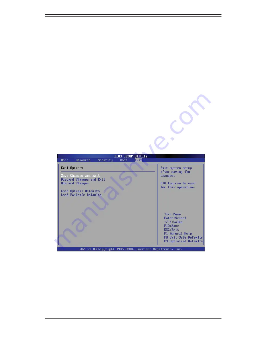
7-6 Exit 

Options

Select the Exit tab from the AMI BIOS Setup Utility screen to enter the Exit BIOS 

Setup screen.

Save Changes and Exit

When you have completed the system confi guration changes, select this option 

to leave the BIOS Setup Utility and reboot the computer, so the new system con-

X

Hard Disk Drives

This feature allows the user to specify the boot sequence from all available hard 

disk drives. The settings are Disabled and a list of all hard disk drives that have 

been detected (i.e., 1st Drive, 2nd Drive, 3rd Drive, etc).

X

Removable Drives

This feature allows the user to specify the boot sequence from available Removable 

Drives. The settings are 1st boot device, 2nd boot device, and Disabled. 

1st Drive

• 

2nd Drive - [USB: XXXXXXXXX]

• 

X

CD/DVD Drives

This feature allows the user to specify the boot sequence from available CD/DVD 

Drives (i.e., 1st Drive, 2nd Drive, etc).

Summary of Contents for SUPERSERVER 5016T-TB

Page 1: ...SUPER USER S MANUAL Revision 1 0a SUPERSERVER 5016T TB...

Page 2: ...for the resolution of any such disputes Super Micro s total liability for all claims will not exceed the price paid for the hardware product FCC Statement This equipment has been tested and found to c...

Page 3: ...811TS 280B chassis Chapter 2 Server Installation This chapter describes the steps necessary to install the SuperServer 5016T TB into a rack and check out the server configuration prior to powering up...

Page 4: ...dvanced Chassis Setup Refer to Chapter 6 for detailed information on the SC811TS 280B 1U rackmount server chassis You should follow the procedures given in this chapter when install ing removing or re...

Page 5: ...v Preface Notes...

Page 6: ...ro 1 5 Chapter 2 Server Installation 2 2 Unpacking the System 2 1 2 3 Preparing for Setup 2 1 Choosing a Setup Location 2 2 Rack Mounting Considerations 2 3 Ambient Operating Temperature 2 3 Reduced A...

Page 7: ...onnecting Power Cables 5 3 Connecting the Control Panel 5 3 5 4 I O Ports 5 4 5 5 Installing the Processor and Heatsink 5 5 Installing an LGA1366 Processor 5 5 Installing a Passive CPU Heatsink 5 7 Re...

Page 8: ...ader 5 18 Onboard Power LED 5 18 Power Supply Fail LED Header 5 19 Alarm Reset 5 19 I Button 5 19 Unit Identifier Button 5 19 5 10 Jumper Settings 5 20 Explanation of Jumpers 5 20 CMOS Clear 5 20 VGA...

Page 9: ...Power Cables 6 6 DVD ROM Drive Installation 6 6 Power Supply Failure 6 7 Chapter 7 BIOS 7 1 Introduction 7 1 Starting BIOS Setup Utility 7 1 How To Change the Configuration Data 7 1 Starting the Setup...

Page 10: ...Notes SUPERSERVER 5016T TB User s Manual x...

Page 11: ...th the 5016T TB as listed below One CPU heatsink SNK P0037P Two 10 cm blower fans FAN 0038L4 One air shroud MCP 310 18009 0N One slim DVD ROM drive DVM TEAC DVD SBT One internal USB cable for DVD ROM...

Page 12: ...C DDR2 1333 1066 800 SDRAM Onboard SATA A SATA controller is built in to the ICH10R portion of the chipset to provide support for a six port 3 Gb sec Serial ATA subsystem The SATA drives are hot swapp...

Page 13: ...1 1 Intersil QPI Up to 6 40 GT s PCI E x16 PCI E Gen2 x16 X58 W83627DHG COM1 COM2 Floppy Kybd Mouse SPI SPI EEPROM ICH10R LPC I O DMI 3 Gb s SATA USB x8 SATA x6 USB 2 0 DDR3 1333 1066 800 LGA1366 CPU...

Page 14: ...portant system monitoring and control information LEDs indicate power on network activity hard disk drive activ ity and system overheat conditions The control panel also includes a main power button a...

Page 15: ...per Micro Computer B V Het Sterrenbeeld 28 5215 ML s Hertogenbosch The Netherlands Tel 31 0 73 6400390 Fax 31 0 73 6416525 Email sales supermicro nl General Information support supermicro nl Technical...

Page 16: ...1 6 SUPERSERVER 5016T TB User s Manual Notes...

Page 17: ...maged in any way If the server itself shows damage you should file a damage claim with the carrier who delivered it Decide on a suitable location for the rack unit that will hold the SuperServer 5016T...

Page 18: ...utions Ensure that the leveling jacks on the bottom of the rack are fully extended to the floor with the full weight of the rack resting on them In a single rack installation stabilizers should be att...

Page 19: ...ble with the manufacturer s maximum rated ambient tempera ture Tmra Reduced Airflow Equipment should be mounted into a rack so that the amount of airflow required for safe operation is not compromised...

Page 20: ...he Sections of the Rack Rails You should have received two rack rail assemblies with the SuperServer 5016T TB Each of these assemblies consist of two sections an inner fixed chassis rail that secures...

Page 21: ...ce when installed and pushed fully into the rack which is its normal position Secondly these tabs also lock the server in place when fully extended from the rack This prevents the server from coming c...

Page 22: ...it The next step is to install the server into the rack Do this by lining up the rear of the chassis rails with the front of the rack rails Slide the chassis rails into the rack rails keeping the pres...

Page 23: ...Telco type rack follow the directions given on the previous pages for rack installation The only difference in the installation procedure will be the positioning of the rack brackets to the rack They...

Page 24: ...e 3 inside of the server Checking the Components You may have one or two processors already installed into the system board 1 Each processor should have its own heatsink attached See Chapter 5 for ins...

Page 25: ...Chapter 2 Server Installation 2 9 Figure 2 5 Accessing the Inside of the System...

Page 26: ...al ATA drives already installed If you need to install Serial ATA drives please refer to the appropriate section in Chapter 6 Checking the Airflow Airflow is provided by two 10 cm input fans The syste...

Page 27: ...re are two push buttons located on the front of the chassis These are in order from left to right a reset button and a power on off button Reset Button The reset button reboots the system Power This i...

Page 28: ...cables and make sure all fans are present and operating normally You should also check to make sure that the chassis covers are installed Finally verify that the heatsinks are installed properly see C...

Page 29: ...n LED When illuminated this green LED on the front of the SATA drive carrier indicates drive activity A connection to the SATA backplane enables this LED to blink on and off when that particular drive...

Page 30: ...3 4 SUPERSERVER 5016T TB User s Manual Notes...

Page 31: ...wer you should first power down the system with the operating system first and then unplug the power cords of all the power supply units in the system When working around exposed electrical circuits a...

Page 32: ...are excellent metal conductors that can create short circuits and harm you if they come into contact with printed circuit boards or areas where power is present Serverboard Battery CAUTION There is a...

Page 33: ...use Touch a grounded metal object before removing the board from the antistatic bag Do not let components or PCBs come into contact with your clothing which may retain a charge even if you are wearing...

Page 34: ...ice is not strictly followed Figure 4 1 Installing the Onboard Battery LITHIUM BATTERY BATTERY HOLDER Please handle used batteries carefully Do not damage the battery in any way a damaged battery may...

Page 35: ...handle them very carefully see previous chapter To prevent the serverboard from bending keep one hand under the center of the board to support it when handling The following measures are generally su...

Page 36: ...uires a chassis big enough to support a 12 x 9 6 serverboard 2 such as Supermicro s SC811TS 280B Make sure that the I O ports on the serverboard align properly with their 3 respective holes in the I O...

Page 37: ...tions Control Panel cable JF1 COM Port cable COM2 Front USB port cable USB2 3 SATA drive data cables SATA0 SATA1 Important Make sure the the cables do not come into contact with the fans Connecting Po...

Page 38: ...arious I O ports Figure 5 1 Control Panel Header Pins Figure 5 2 I O Ports NMI x Key Vcc Vcc Vcc Vcc Vcc UID LED Vcc Reset Button Power Button Ground x Key Power On LED HDD LED UID Switch NIC1 LED NIC...

Page 39: ...ure on the label area of the fan Notes Always connect the power cord last and always remove it before adding re 1 moving or changing any hardware components Make sure that you install the processor in...

Page 40: ...cket or its pins to avoid damaging the CPU or the socket With the CPU in the socket in 4 spect the four corners of the CPU to make sure that it sits level and is properly installed Once the CPU is sec...

Page 41: ...to the heatsink or the CPU die the required amount has al ready been applied Place the heatsink on top 1 of the CPU so that the four mounting holes are aligned with those on the retention mechanism In...

Page 42: ...Using a screwdriver loosen and 3 remove the heatsink screws from the motherboard in the sequence as show in the previ ous section 1 and 2 followed by 3 and 4 Hold the heatsink as shown 4 in the pictur...

Page 43: ...the memory 1 slots starting with DIMM 1A For best performance please use the memory modules of the same type and same speed in the same bank See the DIMM Installation Chart on the following page Note...

Page 44: ...RAM density Memory Population UDIMM 3 DIMMs per Channel Routing DIMM Slots per Channel DIMMs Populated per Channel DIMM Type POR Speeds in MHz Ranks per DIMM any combination SR Single Rank DR Dual Ran...

Page 45: ...op of the card shield to the chassis 3 The PCI slot shield protects the serverboard and its components from EMI and aid in proper ventilation so make sure it is always in place Possible System Memory...

Page 46: ...5 12 SUPERSERVER 5016T TB User s Manual Figure 5 4 X8STi Layout not drawn to scale 5 8 Serverboard Details Notes Jumpers not indicated are for test purposes only...

Page 47: ...Port Header FAN 1 6 Chassis CPU Fan Headers Floppy Floppy Disk Drive Connector I Button I Button Socket for RAID 5 support I SATA0 I SATA5 SATA Ports JAR Alarm Reset Header JD1 Speaker Header JF1 Fro...

Page 48: ...20 Res NC 8 PWR_OK 21 5V 9 5VSB 22 5V 10 12V 23 5V 11 12V 24 COM 12 3 3V Reset Button Pin Definitions JF1 Pin Definition 3 Reset 4 Ground Power Button Pin Definitions JF1 Pin Definition 1 Power Signal...

Page 49: ...Definition 13 Vcc 14 HD Active NIC2 JLAN2 LED The LED connections for JLAN2 are on pins 9 and 10 of JF1 Attach an LED cable to display network activ ity See the table on the right for pin definitions...

Page 50: ...he table on the right for pin definitions NMI Button The non maskable interrupt button header is located on pins 19 and 20 of JF1 Refer to the table on the right for pin definitions NMI Button Pin Def...

Page 51: ...ignated LAN1 and LAN2 are located beside the VGA port on the I O backplane These ports accept RJ45 type cables External Speaker Internal Buzzer On the JD1 header pins 1 4 are for an external speaker a...

Page 52: ...the backplane See the table on the right for pin defini tions SGPIO Header Pin Definitions T SGPIO 0 T TGPIO 1 Pin Definition Pin Definition 1 NC 2 NC 3 Ground 4 DATA Out 5 Load 6 Ground 7 Clock 8 NC...

Page 53: ...y to JPWF to provide a warning of power supply failure This warning sig nal is passed through the PWR_LED pin to indicate of a power failure on the chassis See the table on the right for pin definitio...

Page 54: ...1 CMOS Clear JBT1 is used to clear CMOS which will also clear any passwords Instead of pins this jumper consists of contact pads to prevent accidentally clearing the contents of CMOS To clear CMOS Fir...

Page 55: ...Dog must also be en abled in BIOS Note When enabled the user needs to write their own application software in order to disable the Watch Dog Timer Watch Dog Jumper Settings JWD Jumper Setting Definiti...

Page 56: ...BMC Enable Disable Jumper Settings JBMC1 Settings Definition Pins 1 2 Enabled Pins 2 3 Disabled BMC Enable Disable The JBMC1 jumper allows the user to enable or disable the BMC Base board Management...

Page 57: ...ee the table on the right for more details Onboard Power LED Indicator LE1 LED Color Definition Off System Off power cable not connected Green System on or power cable connected BMC Heartbeat LED A BM...

Page 58: ...Ground 10 Motor Enable 11 Ground 12 Drive Select B 13 Ground 14 Drive Select B 15 Ground 16 Motor Enable 17 Ground 18 DIR 19 Ground 20 STEP 21 Ground 22 Write Data 23 Ground 24 Write Gate 25 Ground 2...

Page 59: ...ed with your motherboard Driver Tool Installation Display Screen Note Click the icons showing a hand writing on paper to view the readme files for each item Click the computer icons to the right of th...

Page 60: ...al system information such as CPU temperature system voltages and fan status See the Figure below for a display of the Supero Doctor III interface Note The default User Name and Password for SuperDoct...

Page 61: ...ded from our Web Site at ftp ftp supermicro com utility Supero_Doctor_III You can also download the SDIII User s Guide at http www supermicro com PRODUCT Manuals SDIII UserGuide pdf For Linux we will...

Page 62: ...5 28 SUPERSERVER 5016T TB User s Manual Notes...

Page 63: ...prevent damage to any printed circuit boards PCBs it is important to handle them very carefully The following measures are generally sufficient to protect your equipment from ESD discharge Precaution...

Page 64: ...ese wires have been bundled together in a ribbon cable to simplify the connection Connect the cable from JF1 on the serverboard to JP4 on the Control Panel PCB printed circuit board Make sure the red...

Page 65: ...eat LED on the control panel You will need to power down the system to replace this fan with one of the same type p n FAN 0038L4 Contact your vendor or Supermicro for information on replacement fans R...

Page 66: ...te Only a slim DVD ROM drive will fit into the 5016T TB Serial ATA Drive Installation The SATA drives are mounted in drive carriers to simplify their installation and removal from the chassis These ca...

Page 67: ...uit board side toward the 1 carrier so that the mounting holes align with those in the carrier Secure the drive to the carrier with four screws as shown in Figure 6 3 2 Installing Removing SATA Drives...

Page 68: ...sp the two handles on either side and pull the unit straight out until it 3 locks you will hear a click Depress the two buttons on the top of the chassis to release the top cover 4 and at the same tim...

Page 69: ...er side and pull the unit straight out until it 3 locks you will hear a click Depress the two buttons on the top of the chassis to release the top cover 4 and at the same time push the cover away from...

Page 70: ...6 8 SUPERSERVER 5016T TB User s Manual Notes...

Page 71: ...be configured Options in blue can be configured by the user The right frame displays the key legend Above the key legend is an area reserved for a text message When an option is selected in the left f...

Page 72: ...selecting the Main tab on the top of the screen The Main BIOS Setup screen is shown below System Overview The following BIOS information will be displayed System Time System Date Use this option to c...

Page 73: ...at For example 5 30 P M appears as 17 30 00 AMIBIOS Version Build Date Processor The AMI BIOS will automatically display the status of processor as shown below Type of Processor Speed Physical Count L...

Page 74: ...bootup screen options to be modified between POST mes sages or the OEM logo Select Disabled to display the POST messages Select Enabled to display the OEM logo instead of the normal POST messages The...

Page 75: ...pt 19 at boot and allow the drives that are attached to these host adaptors to function as bootable disks If this item is set to Disabled the ROM BIOS of the host adap tors will not capture Interrupt...

Page 76: ...n one physical computer The options are Enabled and Disabled Note If there is any change to this setting you will need to power off and restart the system for the change to take effect Please refer to...

Page 77: ...ting is 26 Press or on your keyboard to change this value 2 3 Core Ratio Limit This increases the processor s core 2 3 clock speeds in relation to the bus speed The default setting is 25 Press or on y...

Page 78: ...stalled on an add on card or a network card to handle some or all packet processing of this add on card For this moth erboard the TOE device is built inside the ESB 2 South Bridge chip This feature is...

Page 79: ...orth Bridge to correct correctable memory errors found on a memory module When the CPU or I O issues a demand read command and the read data from memory turns out to be a correctable error the error i...

Page 80: ...nd correct DIMM velocity based on the altitude where the system is located in order to improve DIMM thermal performance Altitude is defined as the number of feet above the sea level where the computer...

Page 81: ...are Disabled and Enabled Active State Power Management Select Enabled to start Active State Power Management for signal transactions between L0 and L1 Links on the PCI Express Bus This maximizes powe...

Page 82: ...ected above Select Intel to enable the Intel SATA Host RAID Utility Select Adaptec to use the Adaptec Host RAID Utility The options are Intel and Adaptec Max Ports on SATA 1 Available if either RAID o...

Page 83: ...KB per interrupt Select Disabled to allow data to be transferred from and to the device one sector at a time Select Auto to allow data transfer from and to the device occur multiple sectors at a time...

Page 84: ...transfer rate of 16 6 MBs It has the same transfer rate as PIO mode 4 and Multi Word DMA mode 2 Select UDMA1 to allow the BIOS to use Ultra DMA mode 1 It has a data transfer rate of 25 MBs Select UDMA...

Page 85: ...ncy to 64 PCI clock cycles The options are 32 64 96 128 160 192 224 and 248 PCI IDE Bus Master When enabled the BIOS uses PCI bus mastering for reading writing to IDE drives The options are Disabled a...

Page 86: ...ices ASK IR Amplitude Shifted Keying Infra Red is a protocol compatible with Sharp branded PDAs and other infra red devices Floppy Controller Select Enabled to enable the onboard Floppy Controller The...

Page 87: ...Hardware Health of the system and review the status of each item when displayed CPU Overheat Alarm This option allows the user to select the CPU Overheat Alarm setting which de termines when the CPU...

Page 88: ...ol TControl 100 C PECI Count TControl CPU Temperature Setting High When CPU PECI count is greater than TControl TControl PECI Count Notes According to Intel s specifications PECI and TControl are defi...

Page 89: ...V 12V 3 3VSB and VBAT XACPI Configuration Use this feature to configure Advanced Configuration and Power Interface ACPI power management settings for your system USB Device WakeUp This feature is used...

Page 90: ...atus of TPM Ownership XIPMI Configuration X8STi F X8STi 3F Only Intelligent Platform Management Interface IPMI is a set of common interfaces that IT administrators can use to monitor system health and...

Page 91: ...wo digit hexa decimal numbers Base 16 0 9 A B C D E F separated by dots i e 00 30 48 D0 D4 60 Subnet Mask Subnet masks tell the network which subnet this machine be longs to The value of each three di...

Page 92: ...options are Disabled and Enabled BMC Watch Dog Timer Action Allows the BMC to reset or power down the system if the operating system hangs or crashes The options are Disabled Reset System Power Down P...

Page 93: ...has not been used and Set means a user password has been entered for the system Change Supervisor Password Select this feature and press Enter to access the submenu and then type in a new Supervisor...

Page 94: ...1st Floppy Drive 2nd Boot Device USB XXXXXXXXX 3rd Boot Device SATA XXXXXXXXX 4th Boot Device Network XXXXXXXXX 5th Boot Device Network XXXXXXXXX Clear User Password Available only if User Password ha...

Page 95: ...allows the user to specify the boot sequence from all available hard disk drives The settings are Disabled and a list of all hard disk drives that have been detected i e 1st Drive 2nd Drive 3rd Drive...

Page 96: ...ss Enter to discard all the changes and return to the AMI BIOS Utility Program Load Optimal Defaults To set this feature select Load Optimal Defaults from the Exit menu and press Enter Then select OK...

Page 97: ...al This section lists Beep Codes for recoverable POST errors Recoverable POST Error Beep Codes When a recoverable type of error occurs during POST BIOS will display a POST code that describes the prob...

Page 98: ...A 2 SUPERSERVER 5016T TB User s Manual Notes...

Page 99: ...ress F6 if you need to install a third 2 party SCSI or RAID driver displays When the Windows XP 2003 Setup screen appears press S to specify ad 3 ditional device s Insert the driver diskette Intel AA...

Page 100: ...er key to proceed with the installation process If you need 5 to specify any additional devices to be installed do it at this time Once all devices are specified press the Enter key to continue with t...

Page 101: ...upported processors Chipset Intel X58 ICH10R chipset BIOS 4 Mb AMI SPI Flash ROM Memory Capacity Six 240 pin DIMM slots that can support up to 24 GB of unbuffered ECC non ECC DDR2 1333 1066 800 SDRAM...

Page 102: ...Temperature 40 to 70 C 40 to 158 F Operating Relative Humidity 8 to 90 non condensing Non operating Relative Humidity 5 to 95 non condensing Regulatory Compliance Electromagnetic Emissions FCC Class...

Page 103: ...anagement Practices Regulations for Perchlorate Materials This Perchlorate warning applies only to products containing CR Manganese Dioxide Lithium coin cells Perchlorate Material special handling may...

Page 104: ...form be reasonably expected to result in significant injury or loss of life or catastrophic property damage Accordingly Supermicro dis claims any and all liability and should buyer use or sell such pr...

Reviews: