
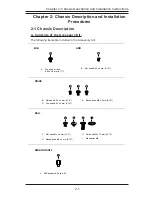


1-16
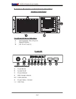
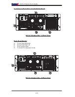
SC743 Chassis
User’s Guide
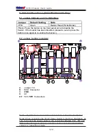
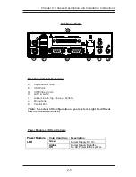
E. SATA743 Back Panel (*SC 743T Only)
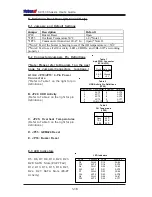
E-1 Jumpers and Default Settings
Jumper Description
Default
JP18 Buzzer
Reset
Open
*JP25
Overheat Temperature 50
o
C
1-2 (*Note 1)
*JP26
Common Act In and Act #0~#7 In
Open (*Note 2)
(*Note1: Test if the buzzer is beeping to see if the OH temperature is >=50
o
C
(*Note2: Test to see if all 8 Activity. LEDs, 8 HDDs, and CBL-0077 are working
properly.)
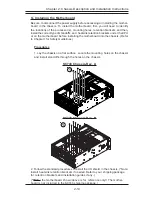
E-2 Connectors/Jumpers Pin Definitions
(*Note: Please refer to Diagram 1 on the next
page for Jumpers/Connectors locations.)
Pins #
1
2 & 3
4
Definition
+12V
Ground
+5V
Table 1
4-pin PWR Connector
(JP10/JP13)
A1/A2. JP10/JP13: 4-Pin Power
Connectors
(*Refer to Table 1 on the right for pin
definitions.)
B. JP26: HDD Activity
(Refer to Table 2 on the right for pin
definitions.)
C. JP25: Overheat Temperatures
(Refer to Table 3 on the right for pin
definitions.)
D. JP35: GEM424 Reset
E. JP18: Buzzer Reset
Table 2
HDD Activity Pin Definitions
(JP26)
Pin Number Definition
1
ACT0
2
ACT1
3
ACT2
4
ACT3
5
COM_ACT
Pin Number Definition
6
ACT4
7
ACT5
8
ACT6
9
ACT7
10
Ground
Pins #
Open
1 & 2
2 & 3
Definition
45
0
C
50
0
C
55
0
C
Table 3
OH Temperature
(JP25)
LED#
Function
D5
FAIL0
D12
ACT0
D6
FAIL1
D13
ACT1
D7
FAIL2
D14
ACT2
D8
FAIL3
D15
ACT3
LED#
Function
D19
FAIL4
D18
ACT4
D20
FAIL5
D21
ACT5
D23
FAIL6
D22
ACT6
D26
FAIL7
D25
ACT7
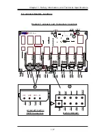
LED Indicators
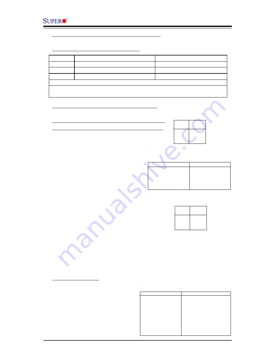
E-3 LED Indicators
D5, D6, D7, D8, D19, D20, D23,
D26: SATA Slots (#0-#7 Fail)
D12, D13, D14, D15, D18, D21,
D22, D27: SATA Slots (#0-#7
Activity)