E-5
Appendix E: SAS-826EL Backplane Specifications
2
1
1
2
+
+
+
+
3
1
1
3
+
+
+
+
+
+
+
+
+
A
C
A
C
A
C
1
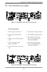
GND
GND
+12V
+5V
GND
GND
+12V
+5V
GND
GND
+12V
+5V
BAR CODE
WWN
SAS826EL
REV 1.02
DESIGNED IN USA
WWN
OVERHEA
TF
AIL1
A
C
BUZZER_ENB1
PRI_MODE4
SEC_MODE4
FANFAIL1
12V_LED 5V_LED
REMOTE_FAN_FAIL_SCOKET
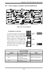
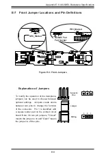
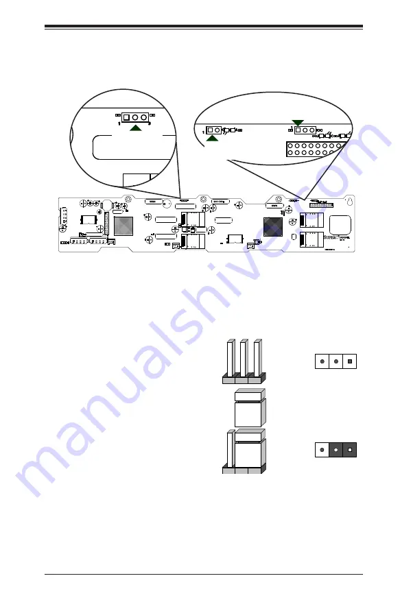
E-7 Front Jumper
Locations and Pin Definitions
Explanation of Jumpers
To modify the operation of the backplane,
jumpers can be used to choose between
optional settings. Jumpers create shorts
between two pins to change the function
of the connector. Pin 1 is identified with
a square solder pad on the printed circuit
board. Note: On two pin jumpers, "Closed"
means the jumper is on and "Open" means
the jumper is off the pins.
Connector
Pins
Jumper
Setting
3 2 1
3 2 1
2
1
1
2
+
+
+
+
3
1
1
3
+
+
+
+
+
+
+
+
+
A
C
A
C
A
C
1
GND
GND
+12V
+5V
GND
GND
+12V
+5V
GND
GND
+12V
+5V
BAR CODE
WWN
SAS826EL
REV 1.02
DESIGNED IN USA
WWN
OVERHEA
TF
AIL1
A
C
BUZZER_ENB1
PRI_MODE4
SEC_MODE4
FANFAIL1
12V_LED 5V_LED
REMOTE_FAN_FAIL_SCOKET
2
1
1
2
+
+
+
+
3
1
1
3
+
+
+
+
+
+
+
+
+
A
C
A
C
A
C
1
GND
GND
+12V
+5V
GND
GND
+12V
+5V
GND
GND
+12V
+5V
BAR CODE
WWN
SAS826EL
REV 1.02
DESIGNED IN USA
WWN
OVERHEA
TF
AIL1
A
C
BUZZER_ENB1
PRI_MODE4
SEC_MODE4
FANFAIL1
12V_LED 5V_LED
REMOTE_FAN_FAIL_SCOKET
SEC_Mode4
PRI_Mode4
Remote Fan
Fail Socket
Figure E-3: Front Jumpers
Summary of Contents for SC847 Series
Page 12: ...SC847 Chassis Manual 1 4 Notes...
Page 32: ...2 20 SC847 Chassis Manual Notes...
Page 53: ...5 15 Chapter 5 Chassis Setup and Maintenance Figure 5 14 Placing the System Fan...
Page 76: ...SC847 Chassis Manual B 2 Notes...
Page 86: ...C 10 SC847 Chassis Manual Notes...
Page 96: ...D 10 SC847 Chassis Manual Notes...
Page 118: ...E 22 SC847 Chassis Manual Notes...
Page 187: ...H 23 Appendix H SAS2 846EL Backplane Specifications Notes...

