SL-PPC-174P4T
User’s Manual
44
Appendix B Programming the Watchdog
Timer
B.1 Programming the Watchdog Timer
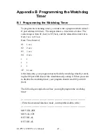
To program the watchdog timer, you must write a program which writes I/
O port address 440 (hex). The output data is a time interval value. The
value range is from 01 (hex) to 3F (hex), and the related time interval is
from 1 sec. to 63 sec.
Data Time Interval
01
1 sec.
02
2 sec.
03
3 sec.
04
4 sec.
ï
ï
ï
ï
ï
ï
3F
63 sec.
After data entry, your program must refresh the watchdog timer by rewrit-
ing the I/O port 440 (hex) while simultaneously setting it. When you want
to disable the watchdog timer, your program should read I/O port 440
(hex).
The following example shows how you might program the watchdog
timer :
;-----------------------------------------------------------------------------------
; Enter the extended function mode , interruptible double-write |
;-----------------------------------------------------------------------------------
MOV DX,2EH
MOV AL,87H
OUT DX,AL
OUT DX,AL
Summary of Contents for SL-PPC-174P4T
Page 1: ...SL PPC 174P4T Pentium 4 processor based panel PC with 17 TFT LCD User s Manual...
Page 8: ...SL PPC 174P4T User s Manual viii...
Page 26: ...SL PPC 174P4T User s Manual 16...
Page 36: ...SL PPC 174P4T User s Manual 26...
Page 37: ...CHAPTER 4 Hardware Installation and upgrading...
Page 44: ...SL PPC 174P4T User s Manual 34 Figure 4 7 Figure 4 8...
Page 45: ...Appendix A Pin Assignments...
Page 56: ...SL PPC 174P4T User s Manual 46 Exit extended function mode MOV DX 2EH MOV AL AAH OUT DX AL...

