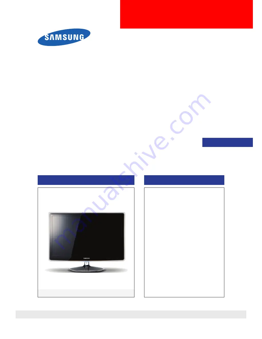
background image

LCD-Monitor

Chassis  : LEM22DS / LEM23DS
Model 

: P2270HD / P2370HD

SERVICE

Manual

TFT-LCD Monitor

Contents

P2270HD / P2370HD

Refer to the service manual in the GSPN (see the rear cover) for the more information.

1. Precautions

2. Product specifications

3. Disassembly and Reassemble

4. Troubleshooting

5. Exploded View & Part List

6. Wiring Diagram

Summary of Contents for P2370HD - Full 1080p HDTV LCD Monitor

Page 1: ...ICE Manual TFT LCD Monitor Contents P2270HD P2370HD Refer to the service manual in the GSPN see the rear cover for the more information 1 Precautions 2 Product specifications 3 Disassembly and Reassemble 4 Troubleshooting 5 Exploded View Part List 6 Wiring Diagram ...

Page 2: ...eshooting 4 1 4 2 No Power 4 2 4 3 PC ANALOG No Screen 4 5 4 4 DVI No Screen 4 8 4 5 HDMI No Screen 4 10 4 6 Faults and Corrective Actions 4 13 4 7 Adjustment 4 14 4 8 How to Access Service Mode 4 14 4 9 White Balance Calibration 4 16 4 10 White Ratio Balance Adjustment 4 18 4 11 Servicing Information 4 19 5 Exploded View Part List 5 1 5 1 Exploded View P2270HD 5 1 5 2 Parts List P2270HD 5 3 5 3 E...

Page 3: ...urope samsungportal com China http china samsungportal com Asia http asia samsungportal com Mideast Africa http mea samsungportal com This Service Manual is a property of Samsung Electronics Co Ltd Any unauthorized use of Manual can be punished under applicable International and or domestic law 2009 Samsung Electronics Co Ltd All rights reserved Printed in Korea P N BN82 00622A 00 ...

Page 4: ...onal Standards Institute ANSI C101 1 Leakage Current for Appliances and Underwriters Laboratories UL Publication UL1410 59 7 With the unit completely reassembled plug the AC line cord directly into a 120V AC outlet With the unit s AC switch first in the ON position and then OFF measure the current between a known earth ground metal water pipe conduit etc and all exposed metal parts including metal...

Page 5: ...trument s ground lead last 1 3 Static Electricity Precautions Some semiconductor solid state devices can be easily damaged by static electricity Such components are commonly called Electrostatically Sensitive Devices ESD Examples of typical ESD are integrated circuits and some field effect transistors The following techniques will reduce the incidence of component damage caused by static electrici...

Page 6: ...om being exposed to moisture Otherwise it may cause a fire or electric shock Make sure to turn the power off and unplug the power cord from the outlet before repositioning the product Also check the antenna cable or the external connectors if they are fully unplugged Damage to the cord may cause fire or electric shock Keep the antenna far away from any high voltage cables and install it firmly Con...

Page 7: ...1 4 1 Precautions Memo ...

Page 8: ...1 kHz Automatic Vertical 56 Hz 75 Hz Automatic Horizontal 30 kHz 81 kHz Automatic Vertical 56 Hz 75 Hz Automatic Display Colors 16 7 Million colors 16 7 Million colors Maximum resolution Horizontal 1920pixels Vertical 1080pixels Horizontal 1920pixels Vertical 1080pixels Input Signal Analog 0 7 Vp p 5 positive at 75Ω internally terminated Analog 0 7 Vp p 5 positive at 75Ω internally terminated Inpu...

Page 9: ...rature 50 C 104 F 10 C 40 C Operating Humidity 10 80 Storage Temperature 4 C 113 C 20 C 45 C Storage Humidity 5 95 Antenna Input 75Ω Sound Characteristic MAX Internal speaker Out Right 3W Left 3W BASS Control Range 8 dB 8dB TREBLE Control Range 8 dB 8 dB Headphone Out 10 mW MAX Output Frequency RF 80 Hz 15 kHz A V 80 Hz 20 kHz ...

Page 10: ... 1 1000 1 Response Time 5ms 5ms Viewing Angle Left Right Up Down 80 80 80 80 Left Right Up Down 80 80 80 80 PC Input D SUB DVI D SUB DVI Power Consumption 51W 54W DPMS Less than 2W Less than 2W Sound Output 3W x 2 3W x 2 Dynamic Contrast Ratio 50000 1 10000 1 Sound Effect Dolby Digital Plus SRS TruSurround HD Dolby Digital Image Size If the resolution is not wide resolution this option allows the ...

Page 11: ...e Control Batteries AAA x 2 BN59 00865A Samsung Electronics Service center Power Cord 3903 000042 Stand Body BN96 09628C Stand Base BN96 11315A D Sub Cable BN39 00244G User s Guide Monitor Driver Natural Color Pro Software BN59 00910C Cleaning Cloth BN63 01798B Holder Cable BN96 06529A ...

Page 12: ...inning the disassembly process 2 When disassembling the monitor do not use any metal tools except for the provided jig 3 Remove the signal cable and the power cord before beginning the disassembly Description Photo Screws 1 Place the monitor face downwards on a soft blanket or cushion as shown in the picture on the right Move the stand from side to side to disassemble it Caution Do not disassemble...

Page 13: ...y and Assembly Description Photo Screws 3 Hold the Front Cover by its corners and push it downwards In the same manner push down on the other corners lift the Rear Cover and disassemble it as shown in the picture below ...

Page 14: ...tion Photo Screws 4 After disassembling the Rear Cover prepare for the internal disassembly as shown in the picture on the right Function SPK Wire LAMP WIRE LVDS 5 Remove the LVDS cable 6 Remove the Lamp wire 7 Remove the Function SPK wires ...

Page 15: ...semble the PCB inside the Assy 10 Remove the Holder Boss from the Assy Front Cover Caution It is difficult disassembling the panel without removing the screws Make sure to remove the screws before removing the Holder Boss 11 Disassemble the panel Reassembly procedures are in the reverse order of disassembly procedures ...

Page 16: ...cate that the monitor is out of scan range or that you need to check the signal cable Environment The location and the position of the monitor may influence the quality and other features of the monitor If there are any sub woofer speakers near the monitor unplug and relocate the woofer to another room Remove all electronic devices such as radios fans clocks and telephones that are within 3 feet o...

Page 17: ...oard and check if a similar symptom appears at another output terminal Diagnostics Main Board Front CN1001 IC1023 IC4010 Yes No Does proper 14 5V appear at pin No 2 of CN1001 Does proper 5V appear at pin No 6 and 7 of CN1001 Check IP Board Yes No Does proper 3 3V appear at pin No 1 of IC1024 Check related circuit of IC1024 No Does proper 14 5V appear at BD1013 Does proper 5V appear at BD1021 Check...

Page 18: ...4 3 4 Troubleshooting 4 2 1 Circuit diagrams when the power does not turn on ...

Page 19: ...4 4 4 Troubleshooting 4 2 2 Waveforms ...

Page 20: ... connector of the panel is connected correctly to the IP board Diagnostics Main Board Front CN1005 CN8003 Yes No Does led persists green light after power on Check IP board Yes No Does proper 5V appear at pin No 9 of CN8003 Check D sub cable connection Yes No Does proper V sync and H sync appear at C809 and C808 Check PC state No Does proper clock signals appear at pin NO 11 12 23 24 of CN1005 Cha...

Page 21: ...4 6 4 Troubleshooting 4 3 1 Circuit diagrams and waveforms Analog when no screen is displayed on the monitor ...

Page 22: ...4 7 4 Troubleshooting 4 3 2 Waveforms ...

Page 23: ...nnector of the LCD panel Diagnostics Main Board Front CN1005 CN901 Yes No Does led persists green light after power on Check IP board Yes No Dose proper 5V appear at pin No 14 of CN901 Check DVI cable connection No Does proper clock signals appear at pin No 2 and NO 4 of RA904 Change RA904 Yes No Does proper clock signals appear at pin NO 11 12 23 24 of CN1005 Change main board because of scaler p...

Page 24: ...4 9 4 Troubleshooting 4 4 1 Circuit diagrams and waveforms DVI No Screen when no screen is displayed on the monitor ...

Page 25: ...s Main Board Front CN1005 CN6009 Yes No Does led persists green light after power on Check IP board Yes No Dose proper 5V appear at pin No 18 of CN6009 Check HDMI cable connection Yes No Does proper signals appear at pin No 15 SCL and No 16 SDA of CN6009 Change IC6002 No Does proper clock signals appear at pin NO 9 and NO 10 of D6005 Change D6005 Yes No Does proper clock signals appear at pin NO 1...

Page 26: ...4 11 4 Troubleshooting 4 5 1 Circuit diagrams and waveforms HDMI No Screen when no screen is displayed on the monitor ...

Page 27: ...4 12 4 Troubleshooting 4 5 2 Waveforms ...

Page 28: ...itor is turned on only a full white pattern is displayed continually regardless of the signals Causes This fault occurs when only the lamp power is supplied and no video signals are input to the panel due to a fault or incorrect connections of the LVDS cable Corrective Actions Replace or reconnect the LVDS cable correctly so that video signals can be supplied to the panel A full white pattern is a...

Page 29: ...Make sure that the power cord is disconnected before replacing any parts 7 To protect aganist shock hazard use an isolation transform 4 8 How to Access Service Mode 4 8 1 Entering Factory Mode To enter Service Mode Press the remote control keys in this sequence If you do not have Factory remote control INFO Power OFF MENU MUTE Power ON If you have Factory remote control PICTURE ON INFO FACTORY The...

Page 30: ...t Effect Off Audio Amp Local Set Other Exhibition Mode Off ADC WB ADC ADC Target ADC RESULT WB Control EDID Sub Option PDP Option Hotel Option Shop Option Sound Config Option Test Pattern Advanced FBE WB Movie EPA Standard ADJUST YC_Delay SHARPNESS PE PQ Others Color Space EEPROM RESET Expert N D ADJ OFF SOURCE Current ...

Page 31: ...t spec 1 Source HDMI 2 Setting Mode 1280 720 60Hz 3 Pattern Pattern 24 Chess Pattern Chess Pattern 4 Use Equipment CA210 Master MSPG925 Generator Use other equipment only after comparing the result with that of the Master equipment Input mode Calibration Pattern AV IN Model_ 1 Perform in NTSC B W Pattern 24 Lattice Component IN Model_ 6 Perform in 720p B W Pattern 24 Lattice PC IN Model_ 21 Perfor...

Page 32: ...ete it returns to the high level menu 8 You can see the change of the Comp Calibration status from Failure to Success Method of Color Calibration PC 1 Apply the VESA XGA Lattice N0 21 pattern signal to the PC IN port 2 Press the Source key to switch to PC mode 3 Enter Service mode 4 Select the Calibration menu 5 Select the PC Calibration menu 6 In PC Calibration Off status press the key to perform...

Page 33: ...ach mode are configured by default Refer to Table 1 2 It varies with Panel s size and Specification 1 2 3 Equipment CA210 Pattern MIK K 7256 92 Flat W B Pattern as standard Use other equipment only after comparing the result with that of the Master equipment Set Aging time 60min Calibration and Manual setting for WB adjustment HDMI Calibration at 24 Chessboard Pattern Manual adjustment 92 pattern ...

Page 34: ... the firmware upgrade into the USB port on the rear of the TV Press the MENU button to display the menu Press the or button to select Support then press the ENTER button Press the or button to select SW Upgrade then press the ENTER button The message Scanning for USB It may take up to 30 seconds is displayed The message Upgrade version XXXX to version XXXX The system will be reset after upgrade is...

Page 35: ... If you select MENU Support Software Upgrade on remote control you ll see below picture 2 Press ENTER then you ll see below picture Select Yes 3 Micom program is now upgrading as below picture After Software Upgrade is process by 100 the monitor is automatically turn off and on ...

Page 36: ...DC Manager Connection 1 Prepare PC to Upgrade the Program 2 Prepare the DDC Manager 3 Connect D sub cable to Target Monitor TV 4 Power on the Target Monitor TV winDDC_V2 39 Program installed Run winDDC 1 2 3 4 PC for MCU upgrading Connect to Parallel port ...

Page 37: ...bleshooting Main MIcom Upgrade 1 Goto installed Program folder winDDC_V2 39 2 Run winDDC 3 Select WinISP Menu 4 Make same setting like picture 5 Choose Flash memory type ECOFIT MFM P2270HD P2370HD WT61P8 3 4 5 1 2 ...

Page 38: ...4 23 4 Troubleshooting 6 Load File Select file to download 7 Set Option to load Binary Files 8 Select files bin file 9 Click button to load files 6 8 7 9 10 Select Flash1 and Flash2 10 ...

Page 39: ...uto Program button 13 If you see OK message Verify program download is completed 11 12 13 After Upgrading Firmware Factory mode 1 Factory remote control SET POWER ON INFO Factory 2 Normal Remote control SET POWER OFF INFO MENU MUTE POWER After Reset Set Power off ...

Page 40: ... Select WinISP Menu 2 Make same setting like picture 3 Choose Device Type ECOFIT MFM P2270HD P2370HD WT61P8 1 3 2 4 Load File Select file to download 5 Set Option to load Binary Files 6 Select files hex file 7 Click button to load files 4 5 6 7 ...

Page 41: ...4 26 4 Troubleshooting 8 Check the OK message Load 9 Click Auto Program button 10 If you see OK message Verify program download is completed 9 10 8 ...

Page 42: ...5 1 5 Exploded View Part List 5 Exploded View Part List 5 1 LS23EMDKU EN Exploded View P2370HD T0003 T0175 M0215 T0514 M0174 M0006 M0013 STD M0027 M0014 ...

Page 43: ...014 BN94 01893Y ASSY PCB MAIN LS23EMDKU EN 1 S A M0027 BN96 11315A ASSY STAND P BASE ECOFIT ROSE BLACK 1 S A M0174 BN44 00226E IP BOARD IP 58155A ECO Ecofit23 24 6 1 S A M0215 BN07 00609A LCD PANEL LTM230HT01 1 S A STD BN96 09628C ASSY STAND P BODY ECOFIT PC ROSE BLACK 1 S A T0003 BN96 11418A ASSY COVER P FRONT LS23EM P2370HD PMMA 1 S A T0175 BN96 06823G ASSY SPEAKER P 16ohm 4pin 3W R 500 L 5 1 S ...

Page 44: ...D T240D T2 2 S N A 3 T0060 BN61 05090A SPRING ETC ECOFIT 23 SK5 T0 5 1 S N A 3 BN61 05091A SPRING ETC STAND ECOFIT 23 SK5 T0 3 1 S N A 3 CCM1 BN63 02183D COVER SHEET Rhcm PE Vinyl T0 05 680mm 20 0 7 S N A 3 M0006 BN63 05796B COVER REAR ECOFIT MFM 23 ABS HB EUROPE 1 S N A 3 M0111 BN63 05798A COVER STAND LS23EM P2370HD ABS HB BK23 1 S N A 3 T0071 BN64 01094A INLAY TERMINAL ECOFIT MFM PS SHEET T0 5 1...

Page 45: ...801B SHIELD COVER ECOFIT MFM 23 SECC T 0 8 EU 1 S N A 2 AA63 01388A GASKET EMI SPONGE SP P300M Conductive Fa 1 S A 0 1 M0113 BN92 04419N ASSY P MATERIAL LS23EMNKU ZA 1 S N A 2 AA01 00004A FOIL 2000 2000 NTR SEH 0 014 S N A 2 BN69 03934A WRAP STRETCH FILM All HDPE 0 012 500 300 0 7 S N A 2 BN81 02321A BAG AIR LIGHT FLEX PLASTIK PE WHITE L120 0 001 S N A 2 T0524 6902 001067 BAG PE HDPE NITRON T0 015...

Page 46: ...5B STAND BAR ECOFIT 23 PMMA CLEAR ROSE BLA 1 S N A 4 BN61 05094A STAND BAR IN P2370 ECOFIT 23 PC CLEAR 1 S N A 4 BN61 05410B STAND BAR A LB650 19 22 PC TRD03 ROSE 1 S N A 5 BN61 02932E BRACKET STOPPER NUT ECOFIT 20 M4 D8 L12 1 S N A 3 CCM1 BN63 02183D COVER SHEET Rhcm PE Vinyl T0 05 680mm 20 0 1 S N A 2 M0027 BN96 11315A ASSY STAND P BASE ECOFIT ROSE BLACK 1 S A 3 6003 001001 SCREW TAPTYPE FH B M3...

Page 47: ...6 1 6 Wiring Diagram 6 Wiring Diagram 6 1 Wiring Diagram Main Board ...

Page 48: ...log DVI HDMI Speaker R Red Speaker L Yellow Audio R L Component RF ANT Headphone Digital Audio Output Optical USB Program Update LVDS Connector Connect with panel Power Connector Connect with IP board PC Stereo Function Connector 8P Connect with function Assy ...

Page 49: ...Main board Receives and transmits the PWM output to the Inverter When a problem occurs The Blank Screen and No Power errors may occur CN5003 Component input terminal When a problem occurs The No MIC Input error may occur JA3201_EU SCART input terminal When a problem occurs The No WebCam Input error may occur CN5011 PC Audio input terminal When a problem occurs The No Speaker Output error may occur...

Page 50: ...6 4 6 Wiring Diagram Memo ...

Reviews: