29
Chapter 4
1.
Detach and remove the metal rear cover.
2.
Remove the two screws of the bracket on the power supply, and
remove it.
3.
Remove the three screws of the power supply, and remove it.
(shown in Fig. 5-1)
4.
Locate the ZIF socket and open it by first pulling the lever side-
ways away from the socket, then upwards at a 90 degrees angle.
5.
Insert the CPU with the correct orientation.
6.
Slide the CPU in gently. It should insert easily. If not, pull the lever
up a little more and make sure the pins of the CPU correspond with
the holes of the socket. DO NOT USE EXCESSIVE FORCE!
7.
Press the lever down. The plate will slide across slightly.
8.
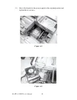
Pull the two levers of the heat sink bracket up.
9.
Connect the CPU fan power cable to the 3-pin connector (FAN1).
(shown in Fig. 5-2)
10.
Put the thermal paste on the surface of the CPU. Place the heat sink
on top of the CPU and fasten it by pulling down the two levers.
(shown in Fig. 5-3).
11.
Move the power supply to the original position and tighten the
three screws.
Caution!
Always disconnect the power cord from your
panel PC when you are working on it. Do not
make connections while the power is on as sen-
sitive electronic components can be damaged by
the sudden rush of power. Only experienced
electronics personnel should open the panel PC.
1
Summary of Contents for SL-PPC-174P4T
Page 1: ...SL PPC 174P4T Pentium 4 processor based panel PC with 17 TFT LCD User s Manual...
Page 8: ...SL PPC 174P4T User s Manual viii...
Page 26: ...SL PPC 174P4T User s Manual 16...
Page 36: ...SL PPC 174P4T User s Manual 26...
Page 37: ...CHAPTER 4 Hardware Installation and upgrading...
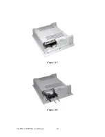
Page 44: ...SL PPC 174P4T User s Manual 34 Figure 4 7 Figure 4 8...
Page 45: ...Appendix A Pin Assignments...
Page 56: ...SL PPC 174P4T User s Manual 46 Exit extended function mode MOV DX 2EH MOV AL AAH OUT DX AL...


