

QUICK START GUIDE
VARIA-SL50
Overview
The AMX VARIA-SL50 (AMX-UTP0501) 5.5” Ultra-Slim, Wall-Mount, Professional-
Grade, Persona-Defined Touch Panel redefines control with personas that fit any
application. Personas include Web Kiosk, Zoom Rooms Controller, AMX Book
Scheduling, and AMX G5 Control.
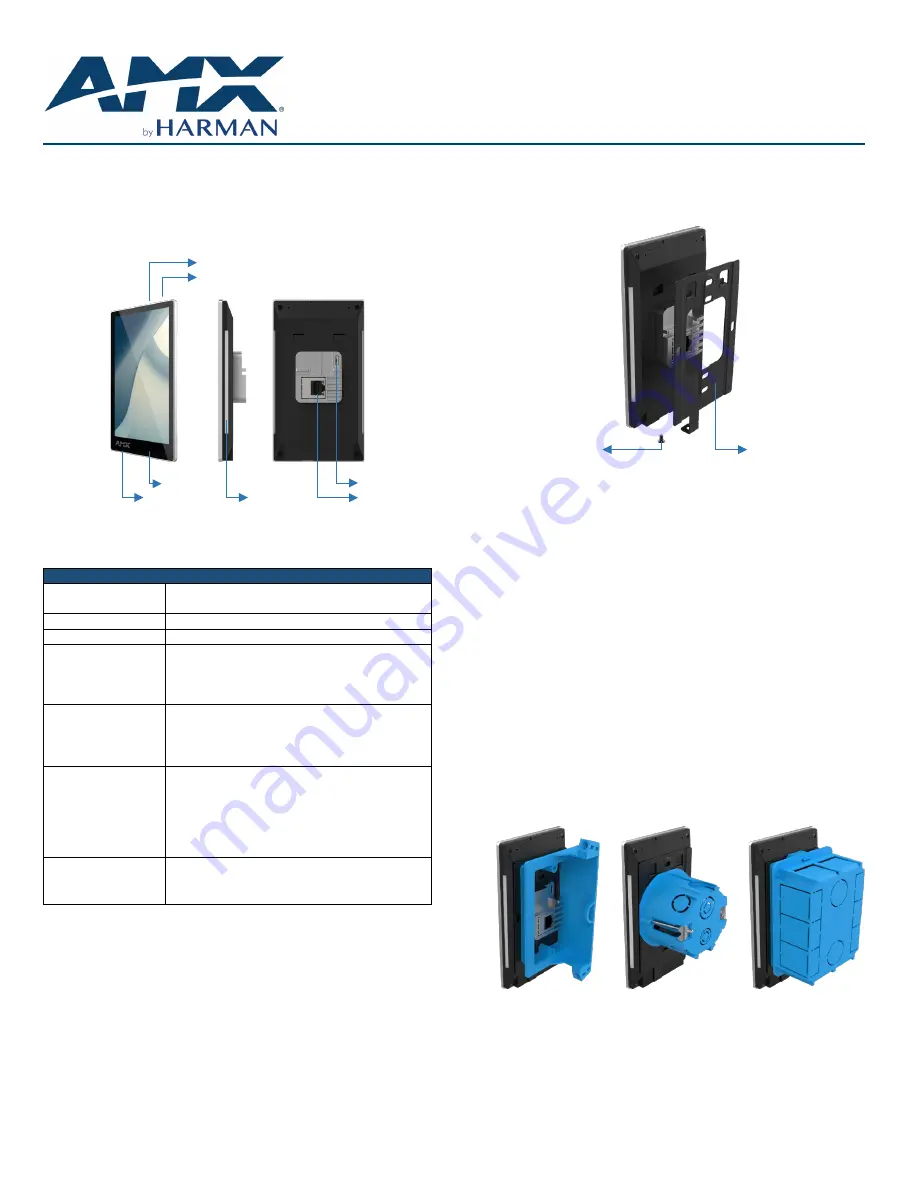
Settings Button
Function Button
Sensors
USB
Microphone
Side LED
LAN/POE
FIG. 1
AMX VARIA-SL50 Touch Panel
Product Specifications
Varia SL50 SPECIFICATIONS
Dimensions (HWD)
5
21
/
32
” x 3
3
/
16
” x
31
/
32
”
(143.4 mm x 80.8 mm x 24.3 mm)
Weight
6.1 oz (173 g)
Power Consumption
PoE, 802.3af, 15.4 watt, compatible w/ PoE+
External Power
Supply Required
Optimal performance requires use of one of the
following AMX PoE power supplies (not included):
•
PS-POE-AF-TC, PoE Injector, 802.3AF
Compliant (FG423-83)
Certifications &
Compliance
•
UL
•
CE
•
CB
•
FCC Class B (-5dB)
Environmental
Operating Temperature
•
0°C - 40° C (32°F – 104°F)
•
5% - 85% Humidity
Storage Temperature
•
-20°C – 60° C (4°F – 140°F)
•
5% - 90% Humidity
Included Accessories
•
Mounting Plate
•
Mounting Hardware
•
Set Screw
VARIA-SL50 Installation
The VARIA-SL50 installs into a standard electrical single gang box (US, UK, EU,
AU) using the included mounting plate.
Power Over Ethernet
Power is supplied via Power Over Ethernet (PoE), utilizing an AMX certified PoE
injector such as the PS-POE-AF-TC PoE Injector (FG423-83) or compatible
network switch which is classified as ES1 and PS2 output in accordance with
IEC/EN/UL 62368-1. Connect the incoming Ethernet cable to the RJ-45 port on
the VARIA-SL50.
Mounting Plate
The included mounting plate contains hole patterns for standard single gang
electrical boxes in US, UK, EU, & AU.
Set Screw
Mounting Plate
FIG. 2
Mounting Plate
STEP 1: Installation Prerequisites
Prior to touch panel installation, install single gang electrical box and properly
terminated category cable (networking cable) in accordance with local laws &
building codes.
STEP 2: Install the Mounting Plate
Screw the mounting plate into standard single gang electrical box using
appropriate hardware for the box.
STEP 3: Route Category Cable
Route the networking cable thru the large central hole in the mounting plate and
plug it into the RJ-45 jack on the back of the touch panel.
STEP 4: Mount the Panel to Plate
Using the top tab & slot, insert the panel into the mounting plate. Make sure
the tabs are fully engaged.
STEP 5: Set Screw
Insert & tighten the set screw on the bottom to secure the panel to the mounting
plate.
FIG. 3
Back Box Installation Examples
Caution: This product is only suitable for installations less than or equal to 2m
(6.56ft) high for CE/UL safety.
Removing
To remove the panel, follow the installation directions in reverse.


