39
Appendix A
A.6 FDD connector (CN10)
Table A.6: FDD connector (CN10)
Pin
Signal
Pin
Signal
1
Vcc(+5V)
14
Step
2
Index
15
GND
3
Vcc(+5V)
16
Write data
4
Drive select
17
GND
5
Vcc(+5V)
18
Write enable
6
Disk change
19
GND
7
NC
20
Track 0
8
NC
21
GND
9
NC
22
Write protect
10
Motor on
23
GND
11
NC
24
Read data
12
Direction
25
GND
13
Density select
26
Side 1 select
Summary of Contents for SL-PPC-174P4T
Page 1: ...SL PPC 174P4T Pentium 4 processor based panel PC with 17 TFT LCD User s Manual...
Page 8: ...SL PPC 174P4T User s Manual viii...
Page 26: ...SL PPC 174P4T User s Manual 16...
Page 36: ...SL PPC 174P4T User s Manual 26...
Page 37: ...CHAPTER 4 Hardware Installation and upgrading...
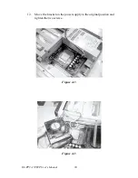
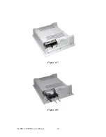
Page 44: ...SL PPC 174P4T User s Manual 34 Figure 4 7 Figure 4 8...
Page 45: ...Appendix A Pin Assignments...
Page 56: ...SL PPC 174P4T User s Manual 46 Exit extended function mode MOV DX 2EH MOV AL AAH OUT DX AL...

