background image

TECHNICAL PASSPORT. INSTALLATION and OPERATION MANUAL

TECHNICAL PASSPORT. INSTALLATION and OPERATION MANUAL

20

The service menu 

comprises only 

and uniquely 

parameters with 

direct impact on 

boiler  combustion 

process, as well as 

on 

heating 

installation management (depending on 

the peripherals management capacity of 

the boiler digital controller unit).

Fuel  switching  and  /  or  change 

the configuration of the heating 

installation  must  be  performed 

by  an  authorized  installer  / 

service.  Some  of  these  reasons 

may affect the safe operation of 

the facility.

9

.3.1.  Cleaning setup

The burner 

performs automatic 

cleaning before 

each  ignition  and 

shut-down.

You can use this menu to adjust the 

running time of the main fan 

(FAN)

 and 

of the cleaning motor 

(Cleaner) - 

not 

active

Select  the  desired  option  using  the 

navigation  arrows.  Use  the  „

Enter

” 

button to open the next parameter. Use 

the 


button to open the next page of 

the menu.

In this submenu 

you can activate or 

deactivate 

the 

automatic  cleaning 

of the burner in 

Ignition 

(Start)

  mode  or  extinguished 

(Stop)

 mode. The checkmark in the box 

indicates  that  the  automatic  cleaning 

system is active.

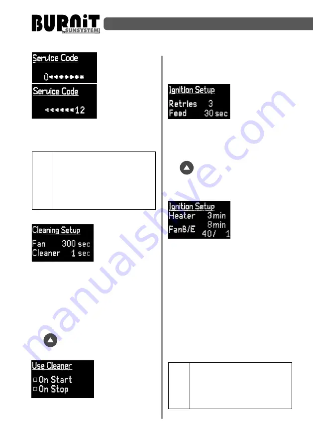
9.3.2. Ignition setup 

In this submenu 

you can set the 

number of attempts 

(

Retries

)    to  ignite 

the burner and the 

time of the initial feed portion of pellets 

(

Feed

).  Select  the  desired  option  using 

the  navigation  arrows.  Use  the  „

Enter

” 

button to open the next parameter. Use 

the 


 button to open the next page of 

the menu.

9.3.3. Cycle setup

Use this submenu 

to adjust the 

running time of the 

heater (

Heater

) and 

the  running  time 

and output of the main fan during the 

ignition of the initial portion of pellets. 

Principle of operation:

After feeding the initial portion of pellets, 

the heater operates for 

3

 minutes , and 

the main fan is turned on at 

40% 

of its 

capacity and operates for 

8

 minutes (the 

heater  continues  to  work).  If  upon  the 

expiration of that period the photosensor 

detects the presence of stable flame, the 

burner enters into operating mode. If no 

stable flame is present, the burner feeds 

in pellets again and repeats the process.

NOTE! Fan B/E 40/1 is a set up 

for the main fan at 40% and set 

up for the fan for fume gases 1% 

(if there is installed). Fan for the 

fume  gases  must  be  connected 

to termonal FSG (see shceme 5).

Summary of Contents for BURNiT Pell 300 Mega

Page 1: ...TECHNICAL PASSPORT INSTALLATION and OPERATION MANUAL FOR AUTHORIZED INSTALLER SERVICE SHOP PELLET BURNER Pell Mega series Version i2 2 EN ...

Page 2: ......

Page 3: ...urner to pellet auger and fuel hopper 10 7 2 Connecting the burner to the mains power supply 11 7 3 Trouble shooting 13 8 OPERATION OF BURNER BURNER 14 8 1 Ignition 14 8 2 Combustion 14 8 3 Automatic cleaning system 14 8 4 Requirements for an authorized installer service 14 8 5 Important recommendation for long lasting and correct operation of the burner 14 9 CONTROLLER UNIT 15 9 1 Controller view...

Page 4: ...per operation of the product 1 2 1 Instructions to boiler installer During installation and operation the country specific requirements and regulations must be observed local construction regulations on installation air supply and exhaust gas extraction as well as chimney connection regulations and norms concerning the fitting of the heating installation with safety devices i Use only original BUR...

Page 5: ...the burner down and clean it Unattended children must not be allowed access to premises with running pellet burner inside It is mandatory to assure a backup power generator of corresponding rated power see 12 2 Safety rules for user operation Operate the pellet burner on recommended fuel only and to that end you must regularly inspect the boiler room Do not use flammable liquids for ignition or in...

Page 6: ...omatic cleaning function and internal pellet auger ensure the automated operation of the burner and optimal burning of the fuel 2 1 Design The burner is made of high quality stainless steel able to withstand temperatures of up to 1150 С The burner must be installed on a heating boiler The burner consists of two parts combustion chamber tube and external tube On the upper part of the burner there i...

Page 7: ...rom the point when the power interruption occurred STB emergency thermostat with probe inserted into the socket of the boiler When boiler temperature is increasing above 100 C the STB thermostat stop the operation of feed screw 3 FUEL All pellets are biomass manufactured from common low growing plants and trees The most common household type pellets are made of sawdust and milled wood chippings wh...

Page 8: ...lated place The optimal pellet ash content is 1 This also provides for less frequent cleaning intervals for the burner The table below contains the parameters which we recommend that you take into consideration when choosing fuel for your Pell Mega burner 4 TRANSPORTATION OF THE PELLET BURNER When loading transporting and unloading of the device appropriate safety equipment must be used in accorda...

Page 9: ...t have direct contact with the ground placed on pallets maximum two tiers and in their original packaging The storage period is not more than 2 years from date of manufacture It is recommended that every burner is tested before installation Quality and safety of the burner must be confirmed by a test mentioned in the warranty card 7 MOUNTING OF THE BURNER Mounting installation and setup of burner ...

Page 10: ...dmium content mg kg 2 0 5 0 5 0 5 Mercury content mg kg 2 0 1 0 1 0 1 Plumbum content mg kg 2 10 10 10 Nickel content mg kg 2 10 10 10 Zinc content mg kg 2 100 100 100 1 Not more than 1 of the pellets may be longer than 40 mm max Length 45 mm 2 Dry weight 3 Particles 3 15 Mm particulate matter before handing over the goods 4 Measurements with lignotester limit value 97 7 by weight 7 1 Pellet burne...

Page 11: ...re it is unplugged during the storms The boiler must be connected to a 220V 50Hz mains using power plug 3 meters long bound to the burner Create tight connection with the electrical mains which complies with the local regulations Diagram 4 Wiring diagram Connection of internal devices to the burner connector FM FSG SF SB PH PWH IGN FC RT PS RB B WH PT OD 1 2 5 7 8 9 10 34 11 12 MAIN FAN Electric m...

Page 12: ...y 220 V N L CH Pump 220 V N L DHW Pump 220 V N L Fuel Feeder Boiler Sensor Sensor Sensor Sensor STB Thermostat Inputs Group 1 RT Room thermostat PS Photo sensor RB Temperature sensor at the top of the buffer B Boiler Group 2 WH Water heater PT Temperature sensor at the bottom of the buffer OD Sensor reverse burning Outputs FM Fan main FSG Fan smoke gases SF Screw fuel SB Screw burner PH Pump heati...

Page 13: ...he manual 3 2 Low performance of the automatic cleaning function 3 2 Increase turn on frequency of the automatic cleaning function 3 3 Improper setting of fuel air mixture 3 3 Adjust using gas analyzer 4 Smoke in the pellet hopper 4 1 Poor chimney draught or high internal resistance of the boiler combustion chamber 4 1 Immediately consult your installer about the problem 4 2 Blockage of burner com...

Page 14: ...d rate thus removing all residues ash noncombustible inclusions etc built up into the combustion chamber of the boiler These automatic cleaning cycles continue depending on the parameters set by the command block The cleaning cycles can be additionally adjusted as well as their repeat rate depending on the load of the burner 8 4 Installer prescriptions regarding burner servicing and maintenance Be...

Page 15: ...he combustion chamber housing 9 CONTROL UNIT 9 1 Controller view Explanation of buttons and indicators LCD screen The controller screen displays the information for the operation of the facility Explanation of buttons Button F function button Apply for exit of the current menu taking back to main screen burner transfer from one condition to another Button Enter apply for switching from one paramet...

Page 16: ...t This symbol means Suspend mode of boiler The notice Hi appearance on the screen where the boiler temperature is displayed means that the measured Boiler body temperature is above 120 C Flashing and beeping alarm is activated When the issue is corrected notification can be deleted When disconnect the boiler from electrical supply for few seconds and then switch on it again boiler goes back to nor...

Page 17: ...burns 5 min at max power followed by transer to power level 2 After 5 min the burner transfers to power level 1 and after 5 min transfers in Suspend mode When there is no signal from room termostat or there is non fullfilled requirement for DHW the burner will fire up In CH DHW mode when DHW Domestic hot water requirement is fullfilled and there is a signal from room termostat the burner burns 5 m...

Page 18: ...ll restart once the water temperature inside the DHW tank drops by 5 C In this way the water temperature inside the DHW tank will be kept at a hysteresis of 5 C i e the water temperature will be between 70 C and 75 C Use UP and DOWN arrow keys in Set Time menu to set the unit s built in timer clock Use UP and DOWN arrow keys in Set Date menu to set the date Use UP and DOWN arrow keys in Contrast m...

Page 19: ...the next screen From this menu you can set up and adjust DHW pump activity periods Use the arrow keys to set time HH MM Use Enter button to checkmark desired time period option If no option is check marked the controller will maintain DHW temperature as a priority Only when its preset value is reached the CH circulation pump will start 9 2 3 Burner shut down Standby Pressing the F button will take...

Page 20: ...he checkmark in the box indicates that the automatic cleaning system is active 9 3 2 Ignition setup In this submenu you can set the number of attempts Retries to ignite the burner and the time of the initial feed portion of pellets Feed Select the desired option using the navigation arrows Use the Enter button to open the next parameter Use the button to open the next page of the menu 9 3 3 Cycle ...

Page 21: ...y three flames You can modify the pellet quantity Feed time interval at which these pellets are fed Cycle and fan output as a percentage value FAN Example with the period set at 10 seconds the pellet auger runs for 2 seconds feeding pellets in the burner and is off for 8 seconds Select the desired option using the navigation arrows Use the Enter button to open the next parameter Use the button to ...

Page 22: ...ext parameter Use the button to open the next page of the menu 9 3 7 Suspend Time In this menu you can adjust the time period for which the burner will remain in suspended mode and the time can be set in minutes with a maximum duration of 180 minutes If within a set time 20 minutes the temperature in the boiler does not decrease the burner enters into Extinguishmode crossed out flame 9 3 8 Cleanin...

Page 23: ...onds and feeds fuel in the burner the internal auger will run for 30 seconds if the setting is Duty 300 see picture Duty parameter can be changed from 0 up to 300 Select the desired option using the navigation arrows Use the Enter button to open the next parameter Use the button to open the next page of the menu This submenu allows you to adjust the conditions under which the p h o t o s e n s o r...

Page 24: ...ner auger feeder 3 CH Central Heating pump 4 DHW Domestic Hot Water pump 5 Ign Ignition 6 CM Cleaning Motor not available Important This menu is for installers only It is active and visible only if the controller is in Standby 10 SETTING OUTPUT MODES OF OPERATION OF THE PELL PELLET BURNER CAUTION You must use gas analyzer when setting the burner The Pell pellet burner is equipped with three step o...

Page 25: ...mber of seconds for setting the operation of the main auger for these 10 sec tFEED 300 000 4 8 x 360 x 56 6 hence tFEED 3 sec where 300 000 is the desired output of the burner in Watts W 56 6 is the heating value of the fuel in kWh kg 360 is the number of burning cycles per 1 hour 56 6 is the amount of pellets in grams fed by the auger per 1 second This way the output mode can be changed and inste...

Page 26: ...l fan setting is tweaked by using gas analyzer to control the oxygen amount registered by the device within the range 8 10 and for the lower modes up to 16 The specific setting depends also on the internal resistance of the boiler combustion chamber on which the burner has been installed as well as on the chimney draught Therefore it is not possible to provide here the exact value for the fan outp...

Page 27: ...0 sec Fan B E 40 40 1 Suspend Feed 2 sec 2 sec Cycle 60 sec 60 sec Fan B E 20 1 25 Suspend Time 0 min 0 min Interm Cleaning Cycle 30 min 60 sec 30 min 60 sec Fan B E 100 1 100 1 Auto Clean Setup P 06 00 P 10 00 P 14 00 P 18 00 P 22 00 P 02 00 Addons Activacion P CH Pump P DHW Pump P Termostat CH Mode P Thermostat Buffer Hardware Setup P Burner Feeder P Cleaning Motor P Tstat NO Vacuum Feeder P NO ...

Page 28: ...LLET BURNER Pell Mega 12 1 Elemets of pellet burner Pell Mega Diagram 7 Elemets of pellet burner Pell Mega 1 Pellet burner Pell Mega 5 Control unit 2 Auger flexible pipe connection 6 Burner housing 3 Auger motor 7 Combustion chamber corps 4 Automatic pellet auger 8 Combustion chamber ...

Page 29: ...ensions Height H Width L Depth D mm 555 1250 420 770 1370 520 Minimal recommended size of boi ler combustion chamber Height Width Depth mm 350 390 550 350 450 550 Required chimney draught Pa 30 30 Heat output adjustment P P Combustion Efficiency Emitted heat 96 93 96 94 Weight of burner kg 90 110 Burner body Length Width Height mm mm 290 550 400 600 Feeder chute Diameter mm 84 84 Built in CPU cont...

Page 30: ... electronic equipment waste disposal thereof is required separately from the normal flow of solid household waste Obsolete equipment shall be collected separately from other recyclable waste containing materials with adverse effect on health and environment Expired appliances must be collected separately from other recyclable waste containing substances hazardous to health and environment Both met...

Page 31: ......

Page 32: ...bg 12 Madara Blvd 9700 Shumen Bulgaria t 359 54 874 555 f 359 54 874 556 e mail ftrade sunsystem bg 13 Chelopeshko Shose Str 1839 Sofia Bulgaria t 359 2 903 97 80 f 359 54 874 556 e mail sales sunsystem bg BG119996Q ...

Reviews: