User Manual
4 Installation Guide
17
At most 8 PV strings can be connected to the PVS-8M-HV and at most 16 PV
strings can be connected to the PVS-16M-HV. If the actual PV string numbers
are less than the nominal numbers, the terminals can be left unconnected. Seal
the unconnected terminals with waterproof plug.
A PV special fuse is set for each string as the upstream protection device of the
whole PV power generation system. Measure the voltage between the positive
and negative polarity of each input before inserting the PVS fuse to make sure
the voltage is within the range of 0
– 1500Vdc. Make sure no PV module string
is connected reversely.
The monitoring board monitors the current of each string. The monitored
current value is sent to the PC through RS485. The PC can judge if a fault is
occurred to the module through the set value.
A SPD is quipped inside the PVS to prevent the transient overvoltage caused
by lightning. The SPD failure signal can be sent to the PC through the RS485.
It must be grounded properly for overvoltage protection. The PVS provides a
ground terminal for equipotential connection.
The PVS will stop operation and the PVS internal monitoring unit will
also stop operation at night or when the sunlight is insufficient and the
PV cell therefore cannot reach the minimum power required by the PVS
for normal operation.
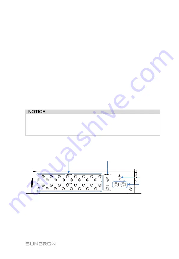
4.4.2 Water-proof terminals and wirings
Water-proof terminals of PVS are shown as followings.
PG-9
M32*1.5
PG-11
PG-11


