Chapter 2
Hardware Installation and Removal
13
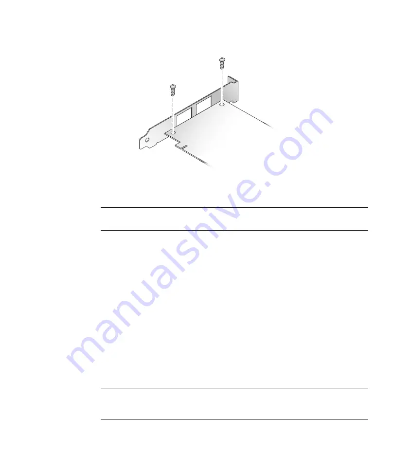
FIGURE 2-1
Removing the Bracket Screws
c. Remove the bracket and store it for future use.
d. Align the new mounting bracket tabs with the holes in the HBA.
Note –
Be careful not to push the bracket past the grounding tabs of the transceiver
housing. Ensure that the LEDs are properly aligned with the holes in the bracket.
e. Replace the screws that attach the HBA to the bracket.
f. Reinstall the SFP(s), if removed in
7. Insert the HBA into the empty PCI Express 8-lane slot.
8. Press firmly until the HBA is seated.
9. Secure the mounting bracket of the HBA to the case with the panel screw or
clip.
10. Replace the system case and tighten the case screws.
The HBA is now installed and you can connect the optical cables.
▼
To Connect the Optical Cable
Note –
The HBA does not allow normal data transmission on an optical link unless
it is connected to another similar or compatible Fibre Channel product (that is,
multimode to multimode).
Summary of Contents for StorageTek SG-XPCIE1FC-QF8-Z
Page 6: ...vi Sun StorageTek 8 Gb FC PCI Express HBA Installation Guide September 2009...
Page 10: ...x Sun StorageTek 8 Gb FC PCI Express HBA Installation Guide September 2009...
Page 20: ...10 Sun StorageTek 8 Gb FC PCI Express HBA Installation Guide September 2009...
Page 46: ...36 Sun StorageTek 8 Gb FC PCI Express HBA Installation Guide September 2009...
Page 48: ...38 Sun StorageTek 8 Gb FC PCI Express HBA Installation Guide September 2009...
Page 50: ...40 Sun StorageTek 8 Gb FC PCI Express HBA Installation Guide September 2009...
Page 53: ...Regulatory Compliance Statements 43...
Page 54: ...44 Sun StorageTek 8 Gb FC PCI Express HBA Installation Guide September 2009...
Page 68: ...58 Sun StorageTek 8 Gb FC PCI Express HBA Installation Guide September 2009...


