Section 7
MAINTENANCE
35
7.1 GENERAL
As you proceed in reading this section, it will be
easy to see that the Maintenance Program for the
air compressor is quite minimal yet important. The
use of the service indicators provided for the fluid
filter, air filter and fluid separator, will alert you when
service maintenance is required. When the mainte-
nance message is displayed by the Supervisor
control, maintenance for that specific item is re-
quir ed. S ee instr u c tions f or eac h item in S ec tion
7.7, Parts Replacement and Adjustment proce-
dur es.
7.2 DAILY OPERATION
Prior to starting the compressor, it is necessary to
check the fluid level in the sump. Should the level
be low, simply add the necessary amount. If the
addition of fluid becomes too frequent, a simple
problem has developed which is causing this ex-
c essive l oss. S ee the
under Excessive Fluid Consumption for a probable
cause and remedy.
After a routine start has been made, observe the
Supervisor control panel and be sure it monitors
the correct readings for that particular phase of op-
eration. After the compressor has warmed up, it is
recommended that a general check of the overall
compressor and Supervisor be made to assure
that the compressor is running properly.
WA R N I N G
!
DO NOT remove caps, plugs, and/or other com-
ponents when compressor is running or pressur-
ized.
Stop compressor and relieve all internal pres-
sure before doing so.
7.3
MAINTENANCE AFTER INITIAL 50
HOURS OF OPERATION
After the initial 50 hours of operation, a few mainte-
nance requirements are needed to rid the system
of any foreign materials if any. Perform the following
maintenance operations to prevent unnecessary
problems.
1. Clean the return line strainers.
2. Clean the return line orifices.
3. Change the fluid filter element.
4. Clean the control line filters.
7.4
MAINTENANCE AFTER 1000
HOURS
After 1000 hours of operation, it will be necessary to
perform the following:
1. Clean the return line strainers.
2. Lubricate the Sullicon Control linkage.
3. Replace the fluid filter element.
7.5 FLUID CHANGE
Standard models are filled with the long life lubri-
cant Sullube 32.
Sullube 32 should be changed under the following
conditions, whichever occurs first:
1. Every 8000 hours.
2. Once a year.
3. As indicated by fluid analysis.
A fluid sample analysis at every 4000 hours is rec-
ommended. Return fluid to Sullair Corporation in
Michigan City for free analysis. To facilitate this, a
sample bottle is included with the compressor.
7.6 SEPARATOR MAINTENANCE
Replace the separator elements when a message
is displayed or after one (1) year, whichever comes
first. The separator elements must be replaced.
DO
NOT
clean the separator elements.
7.7 PARTS REPLACEMENT AND ADJUSTMENT
PROCEDURES
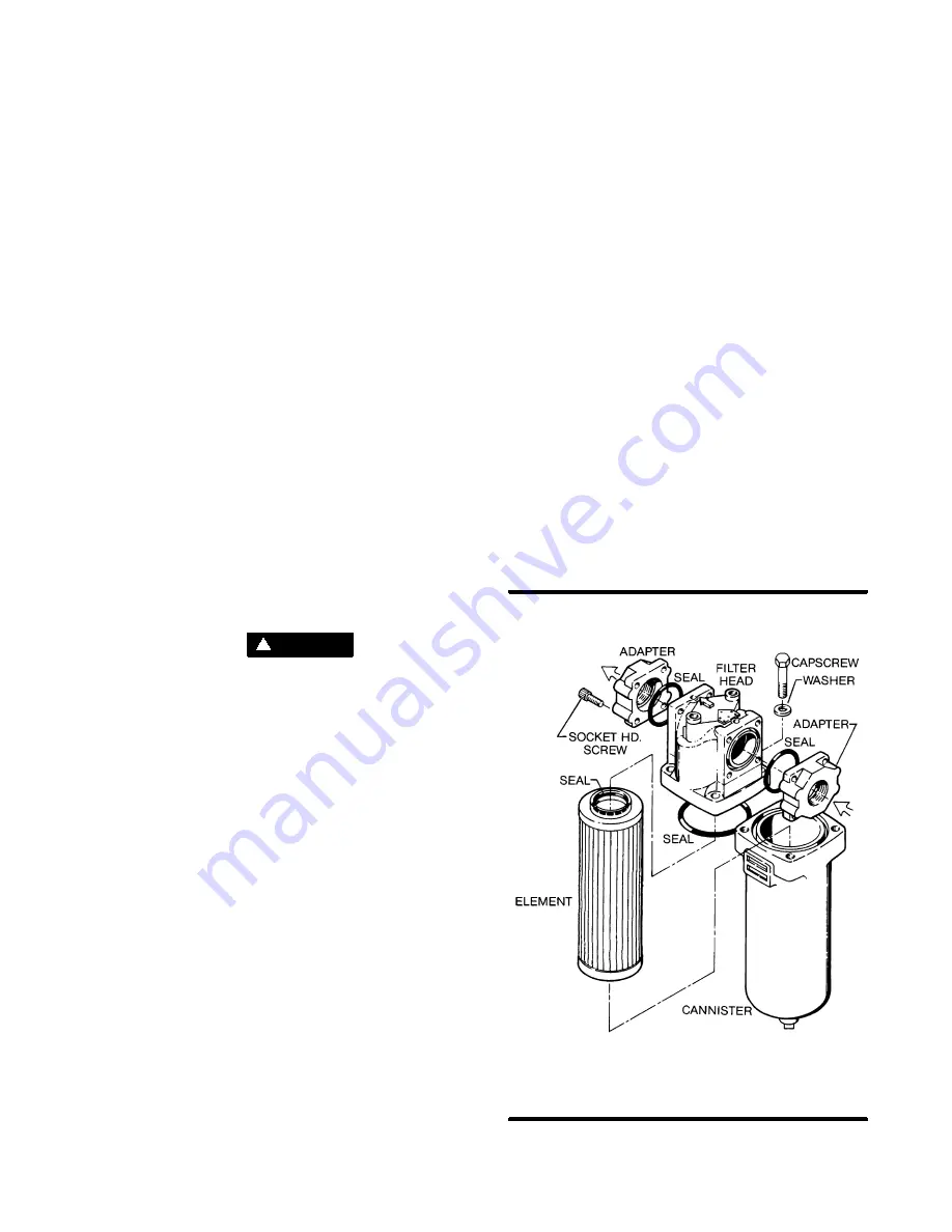
MAIN FILTER MAINTENANCE
Refer to
. The main filter (P/N
250007---219) is located schematically between
the compressor and the fluid stop valve. When
servicing the main filter, shut the compressor
Figure 7---1 Main Filter (P/N 250007---219)
* Repair Kit P/N 250008---956
*
*
*
*
*
Summary of Contents for TS32 Series
Page 2: ......
Page 3: ......
Page 33: ...Section 5 COMPRESSOR SYSTEMS 25 Figure 5 8 Control System 200 250 300HP 150 187 225KW...
Page 34: ...Section 5 COMPRESSOR SYSTEMS 26 Figure 5 8 Control System Diagram 200 250 300HP 150 187 225KW...
Page 35: ...Section 5 COMPRESSOR SYSTEMS 27 Figure 5 9 Control System 400 500 600HP 300 375 450KW...
Page 36: ...Section 5 COMPRESSOR SYSTEMS 28 Figure 5 9 Control System 400 500 600HP 300 375 450KW...
Page 56: ...48 NOTES...
Page 59: ...Section 8 ILLUSTRATIONS AND PARTS LIST 51 NOTES...
Page 62: ...Section 8 ILLUSTRATIONS AND PARTS LIST 54 8 5 MOTOR COMPRESSOR FRAME AND PARTS 400HP 300KW...
Page 66: ...Section 8 ILLUSTRATIONS AND PARTS LIST 58 8 7 AIR INLET SYSTEM 200 300HP 150 225KW...
Page 68: ...Section 8 ILLUSTRATIONS AND PARTS LIST 60 8 8 AIR INLET SYSTEM 400 600HP 300 450KW...
Page 74: ...Section 8 ILLUSTRATIONS AND PARTS LIST 66 8 10 FLUID COOLING SYSTEM 400HP 300KW WATER COOLED...
Page 76: ...Section 8 ILLUSTRATIONS AND PARTS LIST 68 8 10 FLUID COOLING SYSTEM 400HP 300KW WATER COOLED...
Page 126: ...Section 8 ILLUSTRATIONS AND PARTS LIST 118 8 21 SULLICON CONTROL 200 600HP 150 450KW...
Page 128: ...Section 8 ILLUSTRATIONS AND PARTS LIST 120 8 22 COMPRESSOR ACTUATOR 200 600HP 150 450KW...
Page 134: ...Section 8 ILLUSTRATIONS AND PARTS LIST 126 8 24 ENCLOSURE 200 300HP 150 225KW...
Page 136: ...Section 8 ILLUSTRATIONS AND PARTS LIST 128 8 24 ENCLOSURE 200 300HP 150 225KW...
Page 138: ...Section 8 ILLUSTRATIONS AND PARTS LIST 130 8 25 ENCLOSURE 400 600HP 300 450KW...
Page 140: ...Section 8 ILLUSTRATIONS AND PARTS LIST 132 8 25 ENCLOSURE 400 600HP 300 450KW...
Page 142: ...Section 8 ILLUSTRATIONS AND PARTS LIST 134 8 26 RTD PROBES 200 300HP 150 225KW...
Page 144: ...Section 8 ILLUSTRATIONS AND PARTS LIST 136 8 27 RTD PROBES 400 600HP 300 450KW...
Page 146: ...Section 8 ILLUSTRATIONS AND PARTS LIST 138 8 28 AFTERCOOLER 400HP 300KW WATER COOLED...
Page 148: ...Section 8 ILLUSTRATIONS AND PARTS LIST 140 8 28 AFTERCOOLER 400HP 300KW WATER COOLED...
Page 150: ...Section 8 ILLUSTRATIONS AND PARTS LIST 142 8 29 AFTERCOOLER 500 600HP 375 450KW WATER COOLED...
Page 152: ...Section 8 ILLUSTRATIONS AND PARTS LIST 144 8 29 AFTERCOOLER 500 600HP 375 450KW WATER COOLED...
Page 154: ...Section 8 ILLUSTRATIONS AND PARTS LIST 146 8 30 DECAL GROUP...
Page 156: ...Section 8 ILLUSTRATIONS AND PARTS LIST 148 8 30 DECAL GROUP...
Page 158: ...Section 8 ILLUSTRATIONS AND PARTS LIST 150 8 30 DECAL GROUP...
Page 160: ...Section 8 ILLUSTRATIONS AND PARTS LIST 152 8 30 DECAL GROUP...
Page 162: ...Section 8 ILLUSTRATIONS AND PARTS LIST 154 8 31 WIRING DIAGRAM STANDARD FULL VOLTAGE...
Page 163: ...Section 8 ILLUSTRATIONS AND PARTS LIST 155 8 32 WIRING DIAGRAM WYE DELTA...


