Section 6
MAINTENANCE
27
6.1 GENERAL
As you proceed in reading this section, it will be
easy to see that the Maintenance Program for the
air compressor is quite minimal. The use of the
service indicators provided for the fluid filter, air filter
and fluid separator, will alert you when service
maintenance is required. The Supervisor monitors
the status of the fluid filter, air filter and fluid separa-
tor. When maintenance is required, a message will
be displayed indicating the particular maintenance
to be performed as well as a flashing LED on the
graphic map as a visual reminder of the device
needing attention.See instructions for each item in
Section 6.7, Parts Replacement and Adjustment
procedures.
6.2 DAILY OPERATION
Prior to starting the compressor, it is necessary to
check the fluid level in the sump. Should the level
be low, simply add the necessary amount. If the
addition of fluid becomes too frequent, a simple
problem has developed which is causing this ex-
cessive loss. See the Troubleshooting Section (6.8)
under Excessive Fluid Consumption for a probable
cause and remedy.
After a routine start has been made, observe the
various displays and be sure they monitor the cor-
rect readings for that particular phase of operation.
After the compressor has warmed up, it is recom-
mended that a general check of the overall com-
pressor and control panel be made to assure that
the compressor is running properly.
WA R N I N G
!
DO NOT remove caps, plugs, and/or other com-
ponents when compressor is running or pressur-
ized.
Stop compressor and relieve all internal pres-
sure before doing so.
6.3
MAINTENANCE AFTER INITIAL 50
HOURS OF OPERATION
After the initial 50 hours of operation, a few mainte-
nance requirements are needed to rid the system
of any foreign materials which may have accumu-
lated during compressor assembly. Perform the fol-
lowing maintenance operations to prevent unnec-
essary problems.
1. Clean the return line strainers.
2. Clean the return line orifices.
3. Change the fluid filter elements.
4. Clean the control line filters.
6.4
MAINTENANCE
EVERY
1000
HOURS
After 1000 hours of operation, it will be necessary to
perform the following:
1. Clean the return line strainers.
2. Lubricate the Sullicon Control linkage.
3. Replace the fluid filter element.
6.5 FLUID CHANGE
Standard models are filled with the long life lubri-
cant Sullube 32.
Sullube 32 should be changed under the following
conditions, whichever occurs first:
1. Every 8000 hours.
2. Once a year.
3. As indicated by fluid analysis.
For compressors filled with 24KT, the fluid needs to
be changed only when indicated by fluid analysis
or if the fluid has been contaminated.
A fluid sample at every 4000 hours is recom-
mended. Return fluid to Sullair Corporation in
Michigan City for free analysis. To facilitate this, a
sample bottle is included with the compressor.
6.6 SEPARATOR MAINTENANCE
Replace the separator elements when the separa-
tor maintenance message is displayed or after one
(1) year, whichever comes first. The separator ele-
ments must be replaced.
DO NOT
clean the sepa-
rator elements.
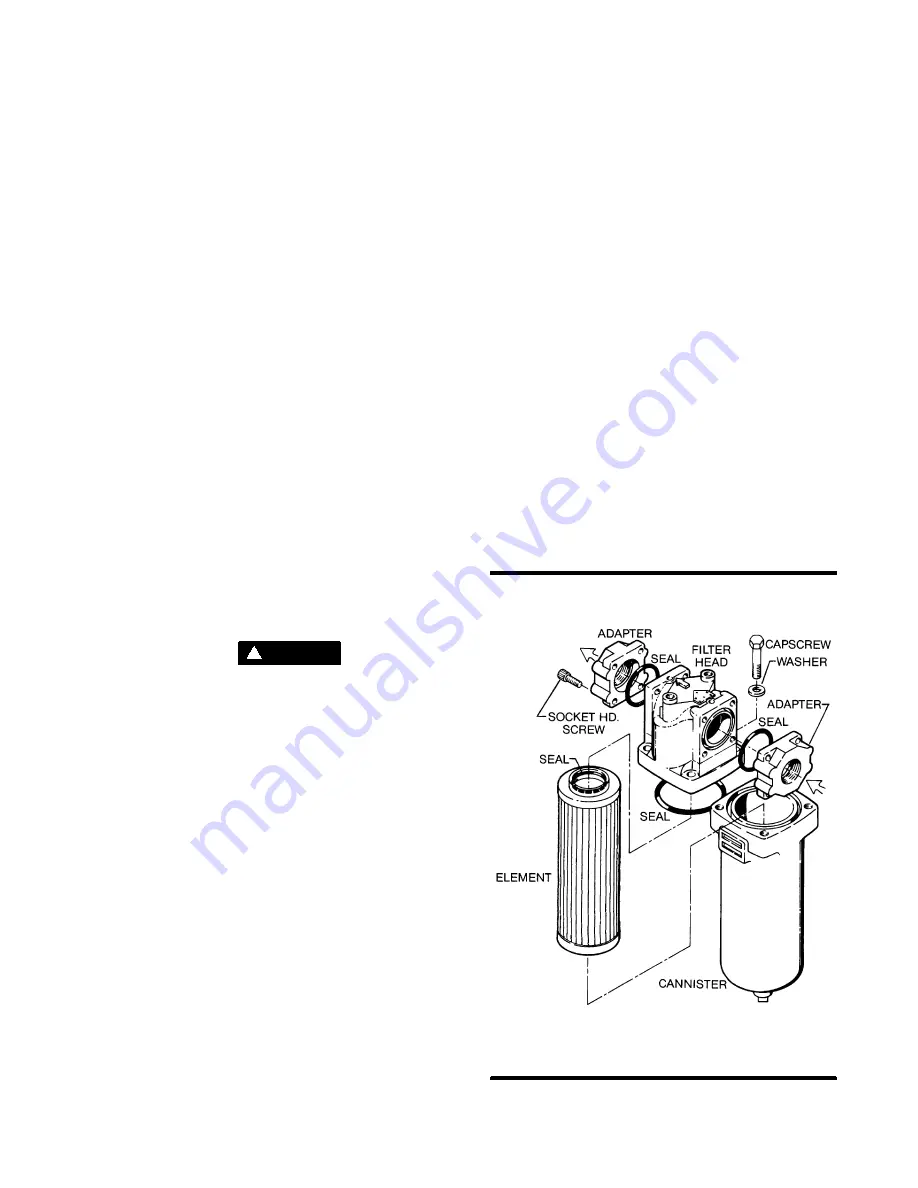
Figure 6---1 Main Filter (P/N 250007---219)
* Repair Kit P/N 250008---956
*
*
*
*
*
Summary of Contents for LS-25S
Page 12: ...Section 2 DESCRIPTION 7 Figure 2 3 Compressor Piping and nstrument Diagram...
Page 16: ...Section 2 DESCRIPTION 11 Figure 2 5A Control System Diagram Start Full Load...
Page 17: ...Section 2 DESCRIPTION 12 Figure 2 5B Control System Diagram Modulation Unload...
Page 49: ...Section 7 ILLUSTRATIONS AND PARTS LIST 44 7 4 COMPRESSOR AIR INTAKE SYSTEM...
Page 71: ...Section 7 ILLUSTRATIONS AND PARTS LIST 66 7 10 COMPRESSOR DISCHARGE SYSTEM...
Page 73: ...Section 7 ILLUSTRATIONS AND PARTS LIST 68 7 10 COMPRESSOR DISCHARGE SYSTEM...
Page 79: ...Section 7 ILLUSTRATIONS AND PARTS LIST 74 7 12 COMPRESSOR ACTUATOR...
Page 81: ...Section 7 ILLUSTRATIONS AND PARTS LIST 76 7 13 ELECTRO PNEUMATIC CONTROL SYSTEM...
Page 83: ...Section 7 ILLUSTRATIONS AND PARTS LIST 78 7 13 ELECTRO PNEUMATIC CONTROL SYSTEM...
Page 85: ...Section 7 ILLUSTRATIONS AND PARTS LIST 80 7 14 ENCLOSURE...
Page 87: ...Section 7 ILLUSTRATIONS AND PARTS LIST 82 7 14 ENCLOSURE...
Page 89: ...Section 7 ILLUSTRATIONS AND PARTS LIST 84 7 15 UNIT TUBING...
Page 91: ...Section 7 ILLUSTRATIONS AND PARTS LIST 86 7 16 DECAL GROUP 1 2 3 4 5 6 7 8 9 10...
Page 95: ...Section 7 ILLUSTRATIONS AND PARTS LIST 90 7 16 DECAL GROUP 21 22 23 24 25...
Page 97: ...Section 7 ILLUSTRATIONS AND PARTS LIST 92 7 16 DECAL GROUP 26 28 29 30 31...
Page 102: ...Section 7 ILLUSTRATIONS AND PARTS LIST 97 7 20 WIRING DIAGRAM...
Page 103: ...Section 7 ILLUSTRATIONS AND PARTS LIST 98 7 21 WIRING DIAGRAM WYE DELTA...


