Section 6
MAINTENANCE
31
for the l oc a tion) . When the j am nut
is loose, turn the adjusting screw clockwise to in-
crease or counterclockwise to decrease the set-
ting.
Above 100 psig (6.9 bar), the spiral valve regulator
should allow pressure to flow into the chamber of
the spiral valve actuator. The spiral valve should
start to rotate at this time.
At approximately 108 psig (7.4 bar), the Sullicon
regulator should allow pressure to flow into the
control chamber of the Sullicon Control. The Sul-
licon Control level should start to move at this time.
Cycle the Control System several times and re-
check all pressure settings.
THERMAL VALVE MAINTENANCE
. For ther mal val v e mainte -
nance, use repair kit number 001084 for standard
compressors and number 001149 for 24KT com-
pressors and follow the procedure explained below
for installation.
1. Remove appropriate piping for disassembly of
the thermal housing.
2. Remove the four (4) capscrews which hold the
housing together and pull the upper housing
away from the lower housing.
3. Remove element.
4. Remove and replace the element seal in the up-
per housing.
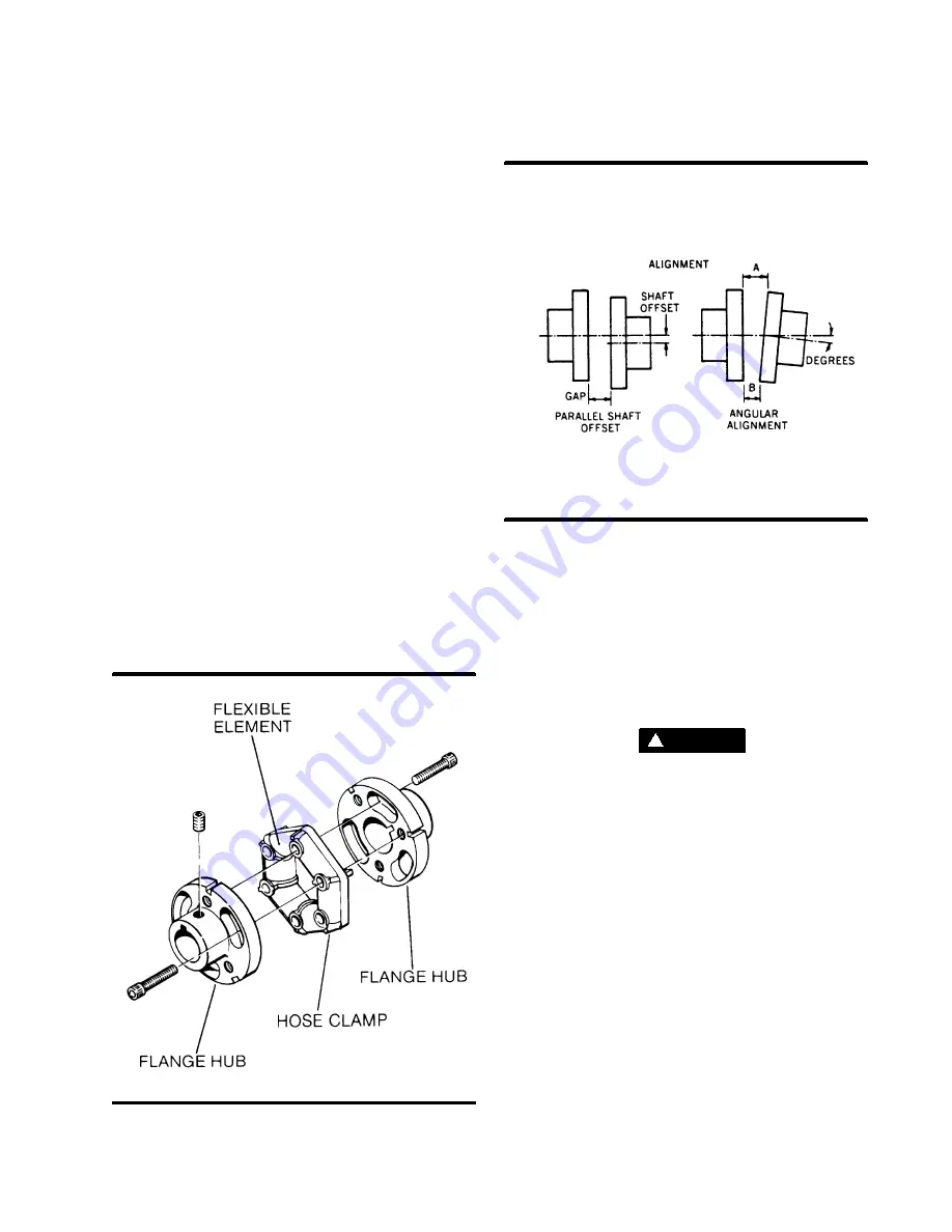
Figure 6---6 Drive Coupling
Figure 6---7 Drive Coupling Alignment
5. Remove and replace the o---rings between the
upper and lower housings.
6. Replace element.
7. Reassemble the housing.
DRIVE COUPLING INSTALLATION AND MAIN-
TENANCE
. F o r c o u p l i n g
installation and alignment, the tools required are a
straight edge, a measuring scale, one set of feeler
gauges, a set of standard Allen wrenches and one
set of standard socket wrenches.
WA R N I N G
!
Disconnect all power at source before attempting
maintenance or adjustments.
For installation and maintenance of the drive cou-
pling, follow the steps explained below.
STEP 1 MOUNT HUBS
--- Mount the motor hub
and the compressor hub onto the respective shaft.
Position the hubs to establish the correct gap
specified in Table 1. Secure each hub with a
setscrew.
STEP 2 OFFSET ALIGNMENT
--- Clean any fluid,
grease, dirt or paint from coupling hubs. Rotate
shafts so that a straight edge will rest squarely (or
within the maximum limit shown in Table 1) on both
flanges and at a point 90
_
away. The vertical offset
alignment is adjusted by the addition or removal of
motor mounting shims. Loosen the motor mount-
ing bolts and slide the motor sideways to correct
the horizontal offset.
STEP 3 COUPLING GAP AND ANGULAR ALIGN-
MENT
--- Position the hubs to establish the proper
Summary of Contents for LS-25S
Page 12: ...Section 2 DESCRIPTION 7 Figure 2 3 Compressor Piping and nstrument Diagram...
Page 16: ...Section 2 DESCRIPTION 11 Figure 2 5A Control System Diagram Start Full Load...
Page 17: ...Section 2 DESCRIPTION 12 Figure 2 5B Control System Diagram Modulation Unload...
Page 49: ...Section 7 ILLUSTRATIONS AND PARTS LIST 44 7 4 COMPRESSOR AIR INTAKE SYSTEM...
Page 71: ...Section 7 ILLUSTRATIONS AND PARTS LIST 66 7 10 COMPRESSOR DISCHARGE SYSTEM...
Page 73: ...Section 7 ILLUSTRATIONS AND PARTS LIST 68 7 10 COMPRESSOR DISCHARGE SYSTEM...
Page 79: ...Section 7 ILLUSTRATIONS AND PARTS LIST 74 7 12 COMPRESSOR ACTUATOR...
Page 81: ...Section 7 ILLUSTRATIONS AND PARTS LIST 76 7 13 ELECTRO PNEUMATIC CONTROL SYSTEM...
Page 83: ...Section 7 ILLUSTRATIONS AND PARTS LIST 78 7 13 ELECTRO PNEUMATIC CONTROL SYSTEM...
Page 85: ...Section 7 ILLUSTRATIONS AND PARTS LIST 80 7 14 ENCLOSURE...
Page 87: ...Section 7 ILLUSTRATIONS AND PARTS LIST 82 7 14 ENCLOSURE...
Page 89: ...Section 7 ILLUSTRATIONS AND PARTS LIST 84 7 15 UNIT TUBING...
Page 91: ...Section 7 ILLUSTRATIONS AND PARTS LIST 86 7 16 DECAL GROUP 1 2 3 4 5 6 7 8 9 10...
Page 95: ...Section 7 ILLUSTRATIONS AND PARTS LIST 90 7 16 DECAL GROUP 21 22 23 24 25...
Page 97: ...Section 7 ILLUSTRATIONS AND PARTS LIST 92 7 16 DECAL GROUP 26 28 29 30 31...
Page 102: ...Section 7 ILLUSTRATIONS AND PARTS LIST 97 7 20 WIRING DIAGRAM...
Page 103: ...Section 7 ILLUSTRATIONS AND PARTS LIST 98 7 21 WIRING DIAGRAM WYE DELTA...


