SECTION 2
EES USER MANUAL
15
OR
• The temperature of the incoming outside
air is
higher
than the set value of the out-
side air temperature controller. Refer to
.
Operation of the rejected and recovered air dampers
is accomplished with use of two position actuator
motors. Only one damper should ever be open at a
given time. When heat is being recovered, the
recovered damper opens while the rejected damper
closes. Conversely when heat is being rejected, the
rejected damper opens while the recovered damper
closes. Both actuators are spring return so when the
compressor does not have power or is on standby,
the actuators return to their normally closed
positions.
2.8
FUNCTIONAL DESCRIPTION
—POWER PRESENT RELAY
A power present relay (
) is used to prevent
unnecessary operation of the EES components. The
EES system will only operate when the compressor
is running. When power is not provided to the
compressor or when the compressor is in standby
mode and not running, there is no power to the EES
controls or motor actuators. Refer to
.
Upon compressor startup, a signal is sent from the
WS controller to the power present relay located in
the EES electrical enclosure. Power is then provided
to the controls and the EES will function normally.
Bypass Air
Damper
To Outside
Incoming Air
Damper
Outside Air
Temperature Sensor
Cooler
Mixed Air
Temperature Sensor
Recovered Air
Damper
Rejected
Air Damper
Figure 2-5: High Outside Temperature
WARNING
When the compressor is on standby there
is still power to the primary and secondary
leads on the transformer in the EES electri-
cal enclosure.
Bypass Air
Damper
Incoming Air
Damper
Outside Air
Temperature Sensor
Cooler
Mixed Air
Temperature Sensor
Recovered Air
Damper
Rejected
Air Damper
Figure 2-6: No Power or Standby
Summary of Contents for 3000 EES
Page 10: ...NOTES 10 ...
Page 16: ...16 BLANK PAGE ...
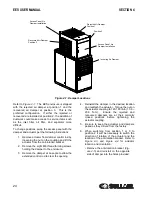
Page 20: ...EES USER MANUAL SECTION 3 20 Figure 3 1 Identification EES 02250175 281 R00 ...
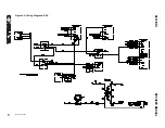
Page 21: ...SECTION 3 EES USER MANUAL 21 Figure 3 2 Wiring Diagram EES 02250175 264 R01 ...
Page 22: ...22 BLANK PAGE ...
Page 28: ...28 BLANK PAGE ...
Page 36: ...36 BLANK PAGE ...
Page 38: ...38 BLANK PAGE ...
Page 44: ...44 BLANK PAGE ...
Page 45: ...Section 8 45 EES USER MANUAL PARTS LISTS ...
Page 46: ...EES USER MANUAL SECTION 8 46 8 1 EES ENCLOSURE ASSEMBLY 02250175 279 R00 ...
Page 48: ...EES USER MANUAL SECTION 8 48 8 2 EES ELECTRICAL CONTROL ASSEMBLY 02250171 648 R00 ...
Page 50: ...EES USER MANUAL SECTION 8 50 8 3 EES DISCHARGE ENCLOSURE ASSEMBLY 02250171 646 R00 ...
Page 52: ...EES USER MANUAL SECTION 8 52 8 4 EES PACKAGE CLEAN AIR INLET OPTION 02250176 044 R00 ...
Page 54: ...54 BLANK PAGE ...
Page 55: ...NOTES 55 ...


