


(April, 2013)
DRH Series GEN1 Ultrasonic Humidifi er Installation, Operation & Maintenance Manual
29
30
31
32
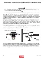
4.4.5 Replacing a Nebulizer Print Plate
1) Referring to Section 4.4.1, “Preparation for Repairs”, place the
water tank on a well lit work surface.
2) Using a 5.5 mm nut driver, remove the print plate mounting nuts
(2 Pcs.) and remove the plate. Save the nuts and insulating parts
to mount the new print plate.
Photo 29
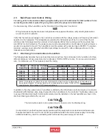
3) Remove the four wires connected to the terminals from the
plate to be replaced.
Photo 30
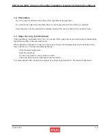
4) Install the new plate together with the silicon sheet provided
using the saved mounting screws.
Photo 31
5) Connect the nebulizer print plate interconnecting wires
(black to H, white to G) and transducer lead wires (orange to
ORG, yellow to YEL)
Note
When the nebulizer print plate is replaced, it is recommended
that the transducer be replaced also.
6) Referring to Sect. 4.4.2, “Re-assembling”, re-assemble the unit
by reversing the procedure described in Section 4.4.1.
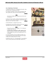
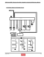
4.4.6 Water Solenoid Valves, Float Switches
and Level Control Board
1) Referring to Section “4.2.2, “Electrical Parts” and “4.2.3 Float
Switches”, remove the electrical access cover and lift the fl oat
panel out.
Photo 32
2) Cut the band bundling the solenoid valve and fl oat switch lead
wires.
Note
Be careful not to damage the lead wires.
3) Unscrew the connecting wires of the parts to be replaced from
the terminal connectors on the level control board.
4.4.6.1
Fill Solenoid Valve
4) To replace the fi ll solenoid valve, remove the pipe fi tting from
the inlet side of the solenoid valve.
5) Turn the fl oat panel over and remove the solenoid valve
mounting screws (2 Pcs.).
Photo 33
6) Remove the elbow on the outlet side and install the new
solenoid valve on the outlet side. Be sure to seal the fi tting with
tefl on tape.
4-11
33