


(April, 2013)
DRH Series GEN1 Ultrasonic Humidifi er Installation, Operation & Maintenance Manual
4-6
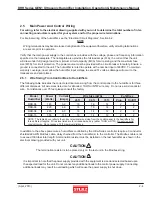
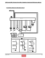
Failure Cause Checking
Remedy
No mist is
generated.
Power supply
system
Control box switch turned
off.
Visually check switch
position.
Turn switch on.
No power to the power
supply.
Measure the voltage
at power supply input
terminals.
Supply power.
Faulty power supply
Replace the
power supply.
Water supply system
Water supply valve is
closed.
Open the valve
Check if the valve is
opened or closed.
Other
Temperature sensor
detects overheating.
Check if ambient tempera-
ture and water temperature
are within specifi ed range.
Correct.
Check voltage at power
supply output terminals.
Amount of mist is
too low.
Supply voltage is low.
Correct the voltage
with the adjustment
screw on the power
supply.
Power supply system
Operating water level is
high and overfl owing.
Water supply control
system
Visually check.
See table 3) on
next page.
Humidifi er is not level.
Other
Visually check.
Correct.
Pull out the fi lter and
visually check.
Clean the fi lter.
‡Air fi lter clogging.
2) If the cause can not be located through the above checking, remove the mist guide cover
and air fl ow guide and check the interior of the water tank.
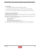
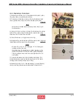
4.3 Troubleshooting and Repair
Should any failure occur, make the necessary repairs referring to the following tables. As a rule, power must
be turned off when troubleshooting is performed but if it is absolutely necessary to troubleshoot when power is
supplied, special attention must be paid to avoid electric shock and short-circuiting.
1) First the humidifi er and its surrounding area should be checked.
Mist supply is
coarse.
Power supply system
Supply voltage is high.
Check voltage at power
supply output terminals.
Fine tune the mist
quality with the
voltage adjustment
screw on the power
supply.
Measure the voltage
at power supply output
terminals.
Remarks:
The causes of failures marked ‡ can be prevented through periodic maintenance/inspection. See Section 4.1, “Periodic
General Maintenance”.
Visually check
the interior of the
water tank.
No mist is
generated.
‡ Dust and foreign material are accumulated in
the water tank.
Clean the interior of the water
tank.
‡ Dust and foreign material are accumulated in
the water tank.
Failure Cause
Checking
Remedy
Clean interior of water tank and
replace the transducer.
Amount of mist is
too low.
‡ Scale deposited on transducer surface.