Stulz DRH-04 Installation, Operation & Maintenance Manual Download Page 16

(April, 2013)

DRH Series GEN1 Ultrasonic Humidifi er Installation, Operation & Maintenance Manual

4-1

4.0  

MAINTENANCE/REPAIRS

4.1     Periodic General Maintenance

Systematic, preventive maintenance of the humidifi er is recommended for optimum system performance. Rou-
tine periodic maintenance should include, but is not limited to the following: 


Tightening electrical connections. 


Cleaning, inspecting the unit’s components visually. 


Checking the level of water and ensuring no leaks are present.

A system should be established to record any problems, defects or defi ciencies noted by operators and discov-
ered during maintenance inspections, together with the actions taken. For assistance, contact STULZ Product 
Support (see Section 5.0). Ensure adherence to all safety precautions while performing any type of mainte-
nance.

4.1.1   General

Before the maintenance inspection and repairs are done, be sure to set the control box power switch to “Off” 
and close the water supply valve.

    WARNING


Turn off power to the unit unless you are performing tests that require power. With power and controls 
energized, the unit could begin operating automatically at any time.

Solid scaffolding must be provided for working in high places.

Care must be taken avoid injury by sharp edges of the sheet metal, etc. 

CAUTION 

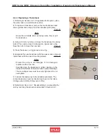
The transducer is a very delicate part. When the water tank interior is cleaned, special care must be taken 
to ensure the transducer is not scratched on the surface with a screwdriver, etc.

Do not supply power to the ultrasonic nebulizer units while the transducer lead wires (yellow and orange) 
are removed. 

Proper tools must be used. Excessive tightening or insuffi cient tightening may cause failure.

When performing maintenance or repairs, care must be taken to ensure small parts such as screws will 
not be lost.

Testing insulation resistance and dielectric withstand voltage should be avoided because the humidifi er 
incorporates sensitive electronic parts. 

When parts are replaced, genuine STULZ parts must be used. Contact STULZ Product Support for 
assistance.

Summary of Contents for DRH-04

Page 1: ...April 2013 DRH Series GEN1 Ultrasonic Humidifier Installation Operation Maintenance Manual MODELS DRH 04 DRH 08 DRH 06 DRH 16 READ AND SAVE THESE INSTRUCTIONS LIRE ET CONSERVER CES INSTRUCTIONS...

Page 2: ...ntains confidential and proprietary information of Stulz Air Technology Systems Inc Distributing or photocopying this document for external distribution is in direct violation of U S copyright laws an...

Page 3: ...1 3 3 Procedure For Operation 3 1 3 4 Precautions 3 2 3 5 Steps for Long Term Shutdown 3 2 4 0 Maintenance Repairs 4 1 4 1 Periodic General Maintenance 4 1 4 1 1 General 4 1 4 2 Maintenance Items and...

Page 4: ...mation A bold text NOTE marks a short message in the information to alert you to an important detail A bold text CAUTION safety alert appears with infor mation that is important for protecting your eq...

Page 5: ...g of the air inlet The humidifier may be filled with the condensed mist and electrical shorts may result CAUTION Observe the unit for water leakage A short circuit could occur if the humidifier is spl...

Page 6: ...original warranty period or for 90 days from the date of installation whichever is greater Stulz Air Technology Systems Inc s warranty does not cover failures caused by improper installation abuse mis...

Page 7: ...r supply temperature 40 F to 104 F Parts to be provided by user DI or RO supply water Water supply valve Water supply tubing 1 4 stainless steel or poly tubing rated for DI water power supply wiring a...

Page 8: ...he water level is near an unsafe level and is closed when the water level is at a minimal level 1 6 5 Fan The 24VDC fan or fans both lightly pressurizes the air above the water to provide a path for t...

Page 9: ...proportional signal is greater than 10 of the maximum input the microprocessor will turn the Solid State Relay on and off in a pulse width modulation control The period of the pulse width is 1 second...

Page 10: ...l Avoid dropping or jarring the unit to prevent damage to the internal parts The unit should always be stored in a dry location prior to installation A Data Package has been sent with your unit It con...

Page 11: ...ht of the unit Weight estimates can be found on the installation drawing provided with your unit Secure the unit with fasteners field supplied by others so that it will not move during operation Ensur...

Page 12: ...side of the humidifier until some resistance is felt Then using an open end wrench on the reducer fitting screw the assembly 1 full turn to fully tighten it DO NOT tighten the filter strainer by gras...

Page 13: ...correct electrical wire sizing from the control panel to the humidifiers for three different distances All wire sizes listed are for stranded THHN or NTW wire only Do not use solid conductor wire For...

Page 14: ...Operation 1 Turn the main power source switch on the control box to the On position 2 Open the water supply valve allowing water to flow to the humidifier 3 Perform a manual drain cycle to flush any...

Page 15: ...teps for Long Term Shutdown If the humidifier is not signalled to turn On for a period of three days the level control board will automatically signal the humidifier to operate a drain cycle When oper...

Page 16: ...ch to Off and close the water supply valve WARNING Turn off power to the unit unless you are performing tests that require power With power and controls energized the unit could begin operating automa...

Page 17: ...Cycle Description Necessary Tools Phillips screwdriver Air filter cleaning About once a week depending on the extent of contamination The interval should be short ened if environmental condi tions are...

Page 18: ...ontrol box disconnect switch to Off and close the water supply valve 2 Loosen the bowl on the filter strainer assembly and remove it Photo 3 3 Remove the element and rinse the filter and the inside of...

Page 19: ...cement 4 2 4 Float Switches 1 Loosen and remove the float panel mounting screws 2 Pcs Photo 8 Note Don t let the screws drop into the tank 2 Lift the float panel out and turn it over Photo 9 3 Check f...

Page 20: ...the air flow guide Photo 13 4 Check the water tank interior for contamination Wipe and clean the water tank interior and clean the surface of the transducers etc in the water tank by wiping with a sof...

Page 21: ...through the above checking remove the mist guide cover and air flow guide and check the interior of the water tank 4 3 Troubleshooting and Repair Should any failure occur make the necessary repairs re...

Page 22: ...ply system overflowing Water supply solenoid valve is faulty Overflowing occurs even after power is turned off 4 Consumable parts Fan lead wires are loose or disconnected from the terminals Clean the...

Page 23: ...ing the parts Photo 19 6 The transducers are visible when you rotate the tank to view the bottom Photo 20 7 The nebulizer print plates are on the side of the tank adjacent to the transducers Photo 21...

Page 24: ...re ties bundling the sensor cable and unscrew the sensor wires from the terminal connectors on the printed circuit board 3 Connect the new sensor wires to the printed circuit board 4 Install the new s...

Page 25: ...e the nuts to mount the new part Photo 27 5 Clean the spacer o ring groove and o ring 6 Assemble the new transducer with the spacer and o ring and install them with the saved mounting screws Photo 28...

Page 26: ...laced it is recommended that the transducer be replaced also 6 Referring to Sect 4 4 2 Re assembling re assemble the unit by reversing the procedure described in Section 4 4 1 4 4 6 Water Solenoid Val...

Page 27: ...rd remove the lead wire terminal connectors 3 Pcs from the board see Photos 6 7 Note Grasp the connectors when removing Never pull the lead wires 10 Slide the level control board out along the guides...

Page 28: ...n UPS ground the customer is responsible for the shipping charges If you do not have established credit with STULZ you must give a freight carrier account number A written or faxed purchase order is r...

Page 29: ...DRAWINGS 6 1 Layout Drawing of Humidifier Covers Removed to Show Parts 1 4 2 8 7 6 5 3 The bubble numbers in the drawing coincide with the item numbers listed below 1 Drain Stub 1 8 NPT 2 Water Supply...

Page 30: ...L NC NO C L M DC DC SolidState Relay 4 3 X 1 X2 PCB Level Controller X1 2 X1 3 X1 5 X2 1 X2 2 X2 3 X2 4 X2 5 X2 6 X2 7 X2 8 X3 1 X3 2 X3 3 X3 4 X3 5 X3 6 X1 6 X1 7 X1 4 X1 8 From Control Box Nebulize...

Page 31: ...lve Solenoid DrainValve Solenoid Fan HighLevel Switch LowLevel Switch OverTemp Sensor BLUE RED X1 1 X X 2 1 X 1 X 2 Current ofRelay 5A 10 12A 1 2 2 1 PinNumber 4 X1 2 X1 3 X1 1 X1 4 X1 2 X1 3 X1 Conne...

Page 32: ...2013 DRH Series GEN1 Ultrasonic Humidifier Installation Operation Maintenance Manual OUD0077D April 2013 DRH Series GEN1 Installation Operation Maintenance Specifictions are subject to change without...

Reviews: