


(April, 2013)
DRH Series GEN1 Ultrasonic Humidifi er Installation, Operation & Maintenance Manual
4-10
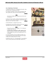
4.4.4 Replacing a Transducer
1) Referring to Section 4.4.1, “Preparation for Repairs”, place
the water tank on a well lit work surface.
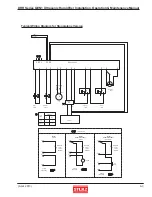
2) To replace a transducer, remove the two transducer lead
wires, (yellow and orange) from the nebulizer print plate.
Photo
26
Note
Grasp the terminals when removing wires. Never pull
the lead wires.
4) Using a 5.5 mm nut driver, remove the transducer mounting
nuts (2 Pcs.) and remove the transducer, spacer and o-ring.
Save the nuts to mount the new part.
Photo 27
5) Clean the spacer, o-ring groove and o-ring.
6) Assemble the new transducer with the spacer and o-ring and
install them with the saved mounting screws.
Photo 28
Notes
Ensure the o-ring is not damaged. If it is damaged,
replace it with a new one.
Carefully align the transducer’s rubber packing in the
indent in the bottom of the water tank to prevent leakage.
The mounting screws must be evenly tightened. Do not
overtighten.
7) Connect the lead wires to the nebulizer print plate. The
colored lead wires must be inserted as shown on the plate.
(Orange wire to ORG, Yellow wire to YEL)
8) Referring to Sect. 4.4.2, “Re-assembling”, re-assemble the
unit by reversing the procedure described in Section 4.4.1.
27
28
26