26
/11.2015/
G17D
1.50
1.45
1.40
1.35
1.30
1.25
1.20
1.15
1.10
1.05
50%
40%
30%
20%
10%
-10
-8
-6
-4
-2
0
2
4
6
8
EN
External water circuit
To seal the water circuit you must connect the unit to a chilled water ring mains, which contains for the generation
of cold water either a chiller, a dry cooler or cooling tower. If the water quality is insufficient, we recommend the
additional installation of a fine mesh strainer.
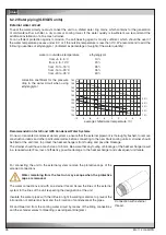
For an efficient protection against corrosion, the anti-freezing agent is mostly sufficient, which should be used if
the water temperature passes under 5°C or if the outside temperature is less than 0°C. We recommend to add the
following quantities of ethylenglycol (indicated as percentage of weight of the water quantity) :
water or outside air temperature
ethylenglycol
from +5 to -5°C
10%
from -5 to -10°C
20%
from -10 to -15°C
28%
from -15 to -20°C
35%
from -20 to -25°C
40%
average chilled water temperature (°C)
correction coefficient for the pressure
drop in the water circuit when using
ethylenglycol
6.2.2 Water piping (GE/GES units)
Connection with external
thread
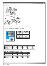
For connecting the unit to the external system remove the protective caps of the
screwed connections.
Water remaining from the test run may escape when the protective
caps are removed.
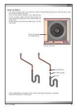
The water connections end with an external thread. Screw the lines of the external
system to the lines of the unit respecting the designation at the unit.
Insulate the water pipes with the diffusion tight insulating material, to prevent the
introduction of ambient air heat and the formation of condensate at the pipes.
Fill and bleed air from the cooling water circuit by means of the filling connections
and the schrader valves for bleeding (see refrigerant diagram).
Recommendation for GE and GES Condenser Water Systems
On new or renovated condenser water systems, ensure that the external pipework is thoroughly flushed, to remove
construction debris and other particulate matter, before connecting to the new Stulz cooling units. A strainer should
be fitted at the unit inlet, to protect the heat exchangers from fouling and possible blockage.
The strainer should have a mesh size of 0.5 mm. Be aware that any fouling or blockage of the heat exchanger result
in a reduced water flow, loss of efficiency, possible damage to the heat exchanger and subsequent unit failure.

