background image

/05.2015/

raisedfloor

7

A

B

B

A

C

D

E

Baugröße

7

A

mm

767,5

B

mm

750

C

mm

3135

D

mm

3072

E

mm

2982

EN

Size

Size 5

Size 7

Summary of Contents for ALR 1082 GE

Page 1: ...STULZ the natural choice Instructions Index G17D Issue 11 2015 CyberAir 3 PRO DX ASR ALR series Precision Air Conditioning Units 380 415 3 50 Original instructions...

Page 2: ...ical Data ASR AS 1 circuit 14 5 7 Technical Data ASR AS 2 circuits 14 5 8 Technical Data ALR GES 1 circuit 15 5 9 Technical Data ALR GES 2 circuits 15 5 10 Dimensional drawings 16 6 Installation 17 6...

Page 3: ...observe the conditions of the power supply companies Switch off the voltage from the unit when working on it Observe the national regulations of the country where the unit will be installed The refrig...

Page 4: ...and the repeated inspection Installation according to EN 378 Operation Determination of emergency measures accidents malfunctions Creation of an abbreviated instruction and notification template page...

Page 5: ...arp edges are al ways protected by rubber grommets Start up Area Cause Danger Safety note In the lower part of the unit refrigerant piping Defective filling line for refrigerant leaks in the refrigera...

Page 6: ...glasses and gloves don t put your head into the unit Pressure lines compressor reheat behind heat ex changer Heat Burns in case of contact to the skin Wear safety gloves Avoid contact to hot unit part...

Page 7: ...nts Construction of protective covering from inside to outside 1 Neopolene cushioning 2 Shrink film 3 Additional board in container shipments 3 2 Transport The Stulz A C units can be moved by lifting...

Page 8: ...ee cooling S units with EC compressor Page code Index number Date of issue month year Language EN English FR French ES Spanish PL Polish IT Italian PT Portuguese RU Russian DE German Energy index 4 De...

Page 9: ...or fall below the dew point of the air This causes dehumidification For a bigger dehumidification the fan speed is reduced With a constant cooling capacity the temperature of the air which flows throu...

Page 10: ...pported by StulzSelect 208V 3Ph 60Hz PE 230V 3Ph 60Hz PE 380V 3Ph 60Hz N PE 460V 3Ph 60Hz PE also for units with speed controlled compressor Other voltages on request Voltage frequency tolerances as f...

Page 11: ...city with an external static pressure 400V 3ph 50Hz 33 C 30 rel h 20 Pa Cooling fluid circuit GE GES Cooling fluid water 30 ethylen glycol Fluid temperature inlet outlet summer operation 34 C 40 C Wat...

Page 12: ...rom m h 13500 16000 18000 19000 20000 22000 21000 27000 32000 R ckluftfilterklasse M5 M5 M5 M5 M5 M5 M5 M5 M5 Schalldruckpegel dBA 49 8 54 2 57 3 55 1 56 5 59 0 53 5 59 6 62 1 Gewicht W rmetauscherein...

Page 13: ...serseitig Winter kPa 57 80 57 96 83 131 168 GE Registerinhalt dm 32 6 37 6 47 3 G Ventilgr e 2 Wege DN 40 40 50 50 50 50 50 GE Ventilgr e 2 Wege DN 40 40 50 50 50 50 50 Luftvolumenstrom m h 10000 1370...

Page 14: ...ewicht W rmetauschereinheit kg 526 555 588 601 671 679 870 Gewicht Ventilatoreinheit kg 162 230 310 397 Gesamtgewicht kg 688 717 818 831 981 989 1267 Baugr e 3 4 5 7 EN 5 6 Technical Data ASR AS 1 cir...

Page 15: ...ntilgr e 2 Wege GE Kreislauf DN 40 40 50 50 50 50 50 Luftvolumenstrom m h 11000 14000 16000 17500 20000 23000 25500 R ckluftfilterklasse M5 M5 M5 M5 M5 M5 M5 Schalldruckpegel dBA 52 1 55 0 52 7 54 2 5...

Page 16: ...gr e B T T N 1 950 890 945 1 2 1400 890 945 1 3 1750 890 945 2 4 2200 890 945 2 5 2550 890 945 3 7 3110 980 1035 4 55 EN 5 10 Dimensional drawings Side view Cabinet size T Depth including main switch...

Page 17: ...uch vibrations install the unit on a vibration absorbing base as it is realized in case of a positioning on a raised floor socket e g by Mafund strips Do not operate the A C unit in office rooms or ot...

Page 18: ...ocket to equalize the height difference Place the heat exchanger unit on the raised floor in front of the cut off for the fan unit Both the heat exchanger unit and the fan unit are equipped with rolls...

Page 19: ...from the front The screws and washers are included drill holes are existant appropriate cage nuts are already installed in the fan unit The M10 screws must be inserted in the lower cross bar on the f...

Page 20: ...from the exterior side of the side panel to the zone of introduction This dimension is decisive if several units are installed fitting exactly side by side AS unit Pressure line Liquid line To design...

Page 21: ...refrigerant connections are located near the compressor and are labelled by the inscriptions pressure pipe and liquid pipe respectively pressure pipe 1 and pressure pipe 2 etc for 2 circuit units The...

Page 22: ...ser this avoids the return flow of refrigerant in to the condenser and a possible low pressure error at the unit start For the hot gas line we recommend to install the non return valve as close as pos...

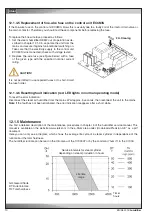
Page 23: ...r Condenser Non return valve option Receiver Safety valve A C unit external installation Open stop valves C7000AT Select the Config menu Enter the password Go to menu Components Manual oper Cooling Va...

Page 24: ...e start The standing refrigerant bottle is connected to the suction side via a pressure gauge station The weight is noted shortly before filling The specified amount of refrigerant is now added when t...

Page 25: ...y of refrigerant filled into the system Read the compressor model on the compressor rating plate If the filled refrigerant quantity exceeds the refrigerant charge limit for the corresponding compresso...

Page 26: ...thread For connecting the unit to the external system remove the protective caps of the screwed connections Water remaining from the test run may escape when the protective caps are removed The water...

Page 27: ...1092 1302 Leitung GES 1 1 2 2 2 2 2 EN Diameter mm ext thread inch Water pipe connection 1 ref circuit in inches Water pipe connection 2 ref circuits in inches Unit GE pipes GES pipes Unit GE pipes T...

Page 28: ...on site after the A C unit has been installed The illustration beside shows an A C unit of the sizes 1 5 with a syphon already installed In A C units of size 7 the condensate drain connection is locat...

Page 29: ...ate line Top view of fan unit Knock out opening for condensate line Put the connection piece from the bottom through the opening into the threaded part of the condensate pipe und screw it tight Put th...

Page 30: ...an unit Screws 4 x M8 Remove the four screws marked in the drawing shown below of the plate on which the inlet cone of the fan is mounted Push the cone support plate at the unit front upwards A and pu...

Page 31: ...water supply authority Drop the plate slantwise on the frame of the fan unit C Push the plate upwards at the side which points towards the condensate pipe Screw the connection piece into the condensat...

Page 32: ...rawings the control cables are marked in green 1 Unscrew both cable feedthrough plates in the heat exchanger unit 2 Route the power cable for the fan and possibly the power cables for the electric hea...

Page 33: ...2 1 3 4 EN Size 2 Size 3 fan power cable connection and distribution for fan power lines Legend 1 fan control cable connection 2 fan power cable connection 3 reheat control cable connection 4 reheat...

Page 34: ...r cable connection and distribution for fan power lines fan power cable connection and distribution for fan power lines Legend 1 fan control cable connection 2 fan power cable connection 3 reheat cont...

Page 35: ...ontrol cable onto the circuit board 7 Plug the control cable for the electric heating to the socket above the power cable of the first e heating The first electric heating is on the right circuit boar...

Page 36: ...lator An inverse rotating field can be detected by a raised compressor noise level and results in overheating and destruction of the compressor after several hours of operation For use of leakage curr...

Page 37: ...he fan unit frame there 2 knock out holes each with a diameter of 59 mm in size 1 and 2 there is only one knock out hole 9 Knock out the necessary quantity of holes for the power supply cable and prov...

Page 38: ...ubber grommets around the cables 12 Now screw the cable feedthrough plates in the heat exchanger unit 13 Tie the excess cable lengths together and stow them away in the frame of the fan unit 14 Re ins...

Page 39: ...11 2015 G17D 39 EN Size 7 control line power supply cable...

Page 40: ...rol circuit fuses and the power switches of the fan and the compressor in sequence Close all doors of the A C unit Switch on the A C unit at the master switch The controller is now supplied with power...

Page 41: ...glass of the liquid line If this is the case refrigerant might have escaped by a leak Check the circuit on leaks eliminate these and top up the circuit with refrigerant in regard of the chapter Mainte...

Page 42: ...D4 Auf 0V gelegt Compressor start stop with ramp ID5 Compressor start stop without ramp ID6 Alarm reset ID7 Serial or pLAN Modbus commutation Dig output Assignation of blocks J12 J13 J14 NO1 not used...

Page 43: ...energize the PC Open terminal ID7 remove the 0V voltage Pull the connector of the ModBus connection from J8 Push the telephone connector of the PGD1 on to block J7 Switch on the PC After the restart...

Page 44: ...e compressor is initialized suitable It is compellingly required to select Yes Following the data is written in the inverter The program verifies the compatibility of Kcompressor and inverter dis play...

Page 45: ...with Prg By the PRG key you come to view M01 the first window in the main menu branch With the Enter key you procede to the next menu Now select M06 BLDC means Brushless direct current Now you must m...

Page 46: ...mum admitted speed on 120 rps In view Co15 you can adjust how the control with a low pressure ratio shall function 1 by closing the expansion valve 2 by increasing the compressor speed Set both parame...

Page 47: ...E PE connection F Operating status LEDs G Terminals for connecting a shunt reactor Setting the network address The network address is composed by the base address which can be mo dified via the ModBus...

Page 48: ...tact up to 240 VAC 3 phase voltage supply Relay K41 for transmission of the HP alarm to the C7000 High pressure switch circuit 1 PC board Terminal Assignation Use 3 0V RS485 ModBus connection 4 RX TX...

Page 49: ...tion measuring the current pressures temperatu res In such a case the unit must only be switched on at the master switch after all mechanical connections have been carried out The unit must be switche...

Page 50: ...itrogen eventually change the filter drier fill with refrigerant according to weight see technical data R410A must be charged in a liquid state in order that the composition of the refrigerant does no...

Page 51: ...nd that the heat exchanger is exposed to the air pollution the particles of which settle at the fins and reduce the heat transmission the same as raise the air resistance The latter shows when the fan...

Page 52: ...the compressor If this difference exceeds 7 K the condenser is probably polluted In this case the condenser has to be cleaned chemically 8 6 Unit in general Electrics Check the connection terminals fo...

Page 53: ...in liquid line defective Modify setting Refill refrigerant Check connection and cable Check setting of low pressure switch Exchange expansion valve Check electric alimentation with voltage meter C7000...

Page 54: ...oil manufacturer Disconnect the depressurized refrigerant pipes from the external system version A AS If glycol or similar additives had been used this liquid also has to be collected and disposed in...

Page 55: ...f the CE Declaration of Conformity The undersigned hereby confirms that the units listed below in the version marketed by us fulfil the requirements of the harmonised EC directives and EC safety stand...

Page 56: ...The undersigned hereby confirms that the units listed below in the version marketed by us fulfil the requirements of the harmonised EC directives and EC safety standards listed below In the case of a...

Page 57: ...ue to lowering of the water level e g because of the evaporation process or drainage the inlet valve opens until the required capacity is available again If the required steam capacity is lower than t...

Page 58: ...opened immediately after having produced steam there is danger of burning when touching the steam cylinder Prevention Before carrying out any work set the steam humidifier OEM2 out of operation as des...

Page 59: ...H3 Green LED Steam production JP1 Jumper block 1 JP2 Jumper block 2 S1 Rotary switch unit type S2 Drain Info key Sx Potentiometer power limitation rH Potentiometer humidity value Y1 Main contactor he...

Page 60: ...ater conductivity 125 S cm Normal water conductivity 125 S cm DSP Exchangeable steam cylinder Cleanable steam cylinder K Fault No 4 steam cylinder maintenance due the unit triggers a warning only the...

Page 61: ...nstallation of an Aqua stop valve in the water supply of the humidifier In ad dition to this the room in which the A C unit with the humidifier is installed should be equipped with a water detection s...

Page 62: ...interval indicates the number of the error see chapter 12 1 4 4 3 Warning and info indication yellow LED in normal operating mode The LED blinks if manual draining is in progress The LED lights if the...

Page 63: ...w hours of operation that the maximum steam output is not achieved This is normal As soon as the water reaches adequate conductivity through the vaporization process the steam humidifier will work at...

Page 64: ...ently info mode The amount of blinks per interval indicates the type of malfunction Yellow LED Warning blinks intermittently A malfunction is present The control unit checks whether there is a tempora...

Page 65: ...more than 72 hours Interval for steam cylinder service exceeded Mineral deposits and or electrodes spent Replace steam cylinder type A clean steam cylinder type D see chapter 5 humidifier service manu...

Page 66: ...stulz com in the e Stulz area under Downloads Precision A C as a pdf document Here you can only see a diagram which shows the average life cycle of a steam cylinder in dependance of the runtime and th...

Page 67: ...via an electrically actuated HW valve The HW valve is controlled via the controller The control parameters are adjusted in the operate compo nents heating HWR valve menu on the controller Refer to the...

Page 68: ...ut of the A C unit The thread sizes for the connection piping of the HW reheat are listed in the following table Malfunction causes Alarm Reheat defect All reheat alarms are received by the controller...

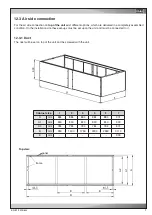
Page 69: ...9 E B A2 A1 A E EN 12 3 1 Duct The duct will be set on top of the unit and be screwed with the unit For the air side connection on top of the unit exist different options which are delivered in a comp...

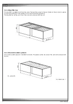
Page 70: ...n of the air which is sucked in and can be obtained in the qualities F6 F7 and F9 according to EN779 The bag filter top will be set on top of the unit and be screwed with the unit 12 3 3 Sound insulat...

Page 71: ...uver with the actuator on the adapter plate Now mount the adapter plate with pre mounted louver on the unit top by means of a screw connection The damper actuator which is controlled via a 24 V signal...

Page 72: ......

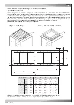
Page 73: ...The joint must be closed by customers with a continuous seal A concrete foundation is recommended in the area of the raised floor supports The raised floor supports have to be installed on vi bration...

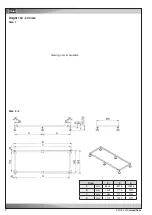
Page 74: ...2 05 2015 raisedfloor A A B C D Baugr e 2 3 4 A mm 662 5 837 5 1062 5 B mm 1425 1775 2225 C mm 1362 1712 2162 D mm 1272 1622 2072 EN Size Height 150 200 mm Size 1 Size 2 4 drawing not yet available...

Page 75: ...05 2015 raisedfloor 3 EN Size 5 Size 7 drawing not yet available...

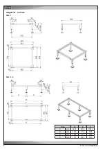
Page 76: ...4 05 2015 raisedfloor A A B C D Baugr e 2 3 4 A mm 662 5 837 5 1062 5 B mm 1425 1775 2225 C mm 1362 1712 2162 D mm 1272 1622 2072 EN Size Height 201 300 mm Size 1 Size 2 4...

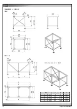
Page 77: ...05 2015 raisedfloor 5 A B B A C D E Baugr e 7 A mm 767 5 B mm 750 C mm 3135 D mm 3072 E mm 2982 EN Size Size 5 Size 7...

Page 78: ...6 05 2015 raisedfloor A A B C D Baugr e 2 3 4 A mm 662 5 837 5 1062 5 B mm 1425 1775 2225 C mm 1362 1712 2162 D mm 1272 1622 2072 EN Size Height 301 400 mm Size 1 Size 2 4...

Page 79: ...05 2015 raisedfloor 7 A B B A C D E Baugr e 7 A mm 767 5 B mm 750 C mm 3135 D mm 3072 E mm 2982 EN Size Size 5 Size 7...

Page 80: ...8 05 2015 raisedfloor A A B C D Baugr e 2 3 4 A mm 662 5 837 5 1063 5 B mm 1425 1775 2227 C mm 1362 1712 2162 D mm 1272 1622 2072 EN Size Height 401 600 mm Size 1 Size 2 4 Side view same as for size 1...

Page 81: ...05 2015 raisedfloor 9 A B B A C D E Baugr e 7 A mm 767 5 B mm 750 C mm 3135 D mm 3072 E mm 2982 EN Size Size 5 Size 7 Side view same as for size 1...

Page 82: ...0 05 2015 raisedfloor A A B C D Baugr e 2 3 4 A mm 662 5 837 5 1063 5 B mm 1425 1775 2227 C mm 1362 1712 2162 D mm 1272 1622 2072 EN Side view same as for size 1 Size Height 601 800 mm Size 1 Size 2 4...

Page 83: ...05 2015 raisedfloor 11 A B B A C D E Baugr e 7 A mm 767 5 B mm 750 C mm 3135 D mm 3072 E mm 2982 EN Size Size 5 Size 7...

Page 84: ...12 05 2015 raisedfloor A C D E A Baugr e 2 3 4 A mm 659 834 1059 B mm 1418 1768 2218 C mm 1362 1712 2162 D mm 1272 1622 2072 EN Size Height 801 1000 mm Size 1 Size 2 4 Side view same as for size 1...

Page 85: ...05 2015 raisedfloor 13 A B B A C D E Baugr e 7 A mm 764 B mm 750 C mm 3128 D mm 3072 E mm 2982 EN Size Size 5 Size 7...

Page 86: ......

Page 87: ...preadjusted 10 seconds power supply 2 is switched onto the unit The unit starts by the automatic restart which is integrated in the controller When the voltage of power supply returns the unit is swi...

Page 88: ...ned current limitation but also for relea sing the overload protection If the current achieves 120 of the adjusted value the overload protection is activated and the voltage supply will be cut With se...

Page 89: ...actory setting both functions are disabled Dip Switch 9 10 t2 for Kickstart Dip Switch 6 7 t3 Reduction time Dip Switch 16 Phase rotation control enabled Phase rotation control disabled With dip switc...

Page 90: ...delayed start of the fans after the damper is opened The image shows the board in the delivery condition all toggle switches for the digital outputs are switched off The assignment of the outputs can...

Page 91: ...5 10 2015 electric EN Wiring diagram of the circuit board...

Page 92: ...045 633 16 35 info stulz it IN STULZ CHSPL INDIA PVT LTD 006 Jagruti Industrial Estate Mogul Lane Mahim Mumbai 400 016 Tel 91 22 56 66 94 46 Fax 91 22 56 66 94 48 info stulz in NL STULZ GROEP B V Post...

Reviews: