background image

SMD-300 Selective Pulse Metal-Detector                       User Manual 

STT Group - Special Technique & Equipment 

 Moscow 

 Russia  45 


NOTE (for reference): To remove the battery

-


Press battery lock downward (#1 on the fig. 46a). 

-


Slide the battery towards oneself (#2 on the fig. 46b ) 

-


Take away the battery from the top plate of the Main unit. 


Press down 

(1) 

Slide (2) 

Take away 
the battery 

Fig. 46a, b 

Summary of Contents for SMD-300

Page 1: ...S SM MD D 3 3 0 0 0 0 S Se e l l e e c c t t i i v v e e P Pu ul l s s e e M M e e t t a a l l D De e t t e e c c t t o or r USER s MANUAL 2011...

Page 2: ...design 13 Main unit front panel 15 Main unit bottom plate 16 Control unit with indication panel 17 SMD 300 controls 18 Main menu operation modes and indication 19 TEST mode 21 COMPENSATION EMI mode 2...

Page 3: ...rities 53 Appendix I SMD 300 battery charge 56 Shipping and storage 62 Certificate of acceptance 62 Warranty 62 For notes 58 PREFACE This User s Manual describes SMD 300 Selective Pulse Metal Detector...

Page 4: ...h sufficient info about inspected object By means of comprehensive software Detector displays the data in a handy form suitable for comparison and analysis For instance unidentified metal object conce...

Page 5: ...etallic items in homogeneous material with regular metallic parts screws bolts holders wall outlets and switches and etc The only condition is 20 alteration of electromagnetic parameters caused by the...

Page 6: ...as its thickness and occurrence depth COMPLETE SET see fig 2 1 Main Unit transceiver module 1 pc 2 Control unit 1 pc 3 Sensor unit with handle 1 pc 4 Headphones 1 pc 5 Imitator test unit 1 pc 6 Rechar...

Page 7: ...SMD 300 Selective Pulse Metal Detector User Manual STT Group Special Technique Equipment Moscow Russia 7 1 2 3 6 7 9 10 11 13 4 5 8 Fig 2 Complete set...

Page 8: ...gnal transmitting modes intensity of emitted magnetic field Pmax Pmin Magnetic field strength at the Sensor unit geometric center 50 A m in a max mode 25 A m in a min mode Probe signal repetition rate...

Page 9: ...parameters evaluation virtual shape dimensions and depth of burial in a uniform medium see Table 1 Table 1 Metallic item Detection range cm Detection Shape evaluation Pmax Pmin Pmax Pmin Imitator tes...

Page 10: ...its 20 and 50 Relative humidity under 25 not more 80 POWER SUPPLY GP VD 153 6 V rechargeable battery Current consumption in max mode not more 0 7 in min mode less then 0 4 Continuous operation time in...

Page 11: ...que Equipment Moscow Russia 11 DIMENSIONS Main unit transceiver 180 135 65 mm Sensor unit 260 mm Control unit with indication panel 260 100 30 mm Standard carrying case 550 450 170 mm WEIGHT in run po...

Page 12: ...of the metallic body that is closer to the sensor and is under the influence of the coils Foucault currents magnetic field is captured by receiving coil of the sensor and processed by build in P Dedi...

Page 13: ...Russia 13 SMD 300 DESIGN SMD 300 Detector represents a portable set that in operational status consists of see fig 5 1 Main unit transceiver module 2 Sensor with a handle 3 Control unit with indicatio...

Page 14: ...que Equipment Moscow Russia 14 Fig 7 SMD 300 Detector Set Clamp Belt Fig 6 Right hand Left hand In operation mode Sensor and Control unit with an indication panel are in an operator s hands while the...

Page 15: ...elective Pulse Metal Detector User Manual STT Group Special Technique Equipment Moscow Russia 15 MAIN UNIT FRONT PANEL 2 3 1 6 4 5 Fig 8 9 Main unit front panel 1 3 2 4 5 Main unit front panel turn ov...

Page 16: ...for connecting Sensor unit 2 5 pin socket DISPLAY for coupling Control unit 3 3 5 PHONE socket for headphones connection 4 Terminal plate for rechargeable battery connection 5 Battery lock 6 Clamp MAI...

Page 17: ...pecial Technique Equipment Moscow Russia 17 1 3 2 4 5 Fig 11 CONTROL UNIT WITH INDICATION PANEL Control unit 1 with indication panel 2 has LCD window 3 and all essential controls 4 with non fastened b...

Page 18: ...w Russia 18 SMD 300 CONTROLS 1 POWER ON OFF switch button 2 AXIS button for parameters scale adjustment on a built in graphic display 3 DATA button for data transfer to PC coupled to the Detector 4 cu...

Page 19: ...l Technique Equipment Moscow Russia 19 MAIN MENU OPERATIONAL MODES AND INDICATION After switching on the device the inscription SELECTIVE METALL DETECTOR SMD 300 appears on a screen fig 13 3 5 sec lat...

Page 20: ...compensation mode NOTE Noise compensation should be carried out every time after switching on the device or switching over transmitter s output power Pmax Pmin In this case the following interferences...

Page 21: ...f the screen 2 3 s later the label will be displayed certainly if the device is in a working condition COMPENSATION EMI operating mode After activating mode 2 the inscription COMPENSATION EMI appears...

Page 22: ...stigated NOTE If the battery icon is empty immediately replace it Horizontal axis Z corresponds to the item s occurrence depth Zmax 20 in the upper part of the screen represents the maximum occurrence...

Page 23: ...m for the sample displayed NOTE N ATT symbols and their values are displayed automatically by Detector s Processor N parameter from 0 to 3 is a conventional value that corresponds to relative complexi...

Page 24: ...cow Russia 24 ATT active attenuation value is displayed by convention from 0 to 4 0 signifies that input signal exceeds receiver s noise level but not more then 60 dB Every step 1 corresponds to autom...

Page 25: ...l Technique Equipment Moscow Russia 25 Fig 20 Fig 21 Fig 22 DETECTED ITEMS GRAPHIC DISPLAY Detected item is displayed by convention in a certain virtual graphic form depending on its size thickness an...

Page 26: ...se but small item Deep item s occurrence depth Fig 24 or I BLINKING CONCENTRIC CIRCLES Blinking concentric circles in a geometric centre of display window confirm the detection of metallic item fig 23...

Page 27: ...ic plate N 1 At that Position of that line on Z axis Z co ordinate corresponds to item s occurrence depth Line s height corresponds to an average plate s Cross cut size Line s thickness corresponds to...

Page 28: ...ective Pulse Metal Detector User Manual STT Group Special Technique Equipment Moscow Russia 28 Fig 28 Questioned item Occurrence depth Detected item to be represented as virtual single metallic plate...

Page 29: ...e Equipment Moscow Russia 29 Cross cut size of a virtual plate corresponds to the height of vertical line on a screen see fig 25 27 Plate s thickness corresponds to the line s thickness on a screen De...

Page 30: ...sition of the left border of that rectangular corresponds to the item s occurrence depth Rectangle s height corresponds to an average cross cut item s dimension i e dimension of the surface close to d...

Page 31: ...User Manual STT Group Special Technique Equipment Moscow Russia 31 Detected item of an intricate shape to be represented as two or tree virtual metallic plates see fig 32a Fig 32 Occurrence depth D1...

Page 32: ...Detected item fig 32 of an intricate shape represented as two or tree virtual metallic plates Cross cut size of virtual plate corresponds to the size of item s nearest border D1 Fig 32a Occurrence dep...

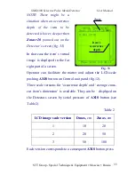
Page 33: ...isplayed in the far right part of a screen Operator can facilitate the matter and adjust the LCD scale pushing AXIS button on Control unit panel fig 12 Three scale versions for occurrence depth and av...

Page 34: ...e blinking cursor to select operational mode you prefer just press corresponding button and then ENTER button 1 and 2 on fig 35 In that way 1 Pmax Pmin is intended for switching over the probe signal...

Page 35: ...r to the 2 nd position and press ENTER button The word Graph or Text appears on the screen in confirmation In a Graph mode fig 36 the detected item s parameters are displayed in a graphic form as a di...

Page 36: ...consists of item s parameters conformed to each plate see fig 37 for your reference The following item s parameters are displayed on a screen T mks time parameter microsecond NOTE Time parameter valu...

Page 37: ...cial Technique Equipment Moscow Russia 37 Fig 38 a b c Z cm occurrence depth W mm virtual plate thickness On the fig 38a b c depicted for one s reference one can see the table of parameters when no it...

Page 38: ...e is 50 NOTE After switching on SMD 300 Detector the audio signal level in the headphones is automatically adjusted to 50 of a possible maximum level To adjust the volume in the headphones from 0 to 1...

Page 39: ...re is intended for SMD 300 team work with PC Data obtained during the operation signal level and other parameters can be transferred to PC via serial RS 232 port Couple Main unit to serial port of PC...

Page 40: ...reveal any alteration of average physical parameters for the structure under control For example secondary metallic item that was built into a regular reinforced wall structure SMIF software searching...

Page 41: ...nditions the instrument should be kept unpacked at a working temperature for at least 2 hours USEFUL HINTS To obtain the maximum sensitivity of the instrument it is highly recommended to switch off ev...

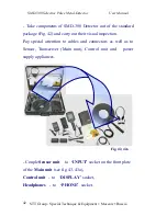
Page 42: ...he standard package Fig 42 and carry out their visual inspection Pay special attention to cables and connectors as well as to Sensor Transceiver Main unit Control unit and power supply appliances Coup...

Page 43: ...Special Technique Equipment Moscow Russia 43 Fig 43 43a Fig 44 SMD 300 POWER SUPPLY Take fully charged battery see Battery Charger User s Manual for reference Couple rechargeable battery to a corresp...

Page 44: ...nsceiver body vertically with battery lock towards oneself fig 45a Place the battery on top of the Main unit battery terminal plate Press down 1 on the fig 45b and slide it away from oneself 2 on the...

Page 45: ...e Equipment Moscow Russia 45 NOTE for reference To remove the battery Press battery lock downward 1 on the fig 46a Slide the battery towards oneself 2 on the fig 46b Take away the battery from the top...

Page 46: ...e fig 6 for reference Put on headphones Grasp Control unit with one hand while sensor unit with another see fig 7 for reference Press POWER button 1 on fig 12 to switch on Detector Use and ENTER butto...

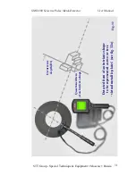
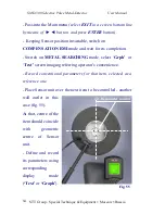
Page 47: ...unding metallic items Fig 48 Press and ENTER buttons to activate COMPENSATION EMI mode in the Main menu fig 14 and 16 and wait for its completion Activate METAL SEARCHING mode and graphic mode Grph in...

Page 48: ...tallic item closer to the SMD 300 sensor so that flickering concentric circles appear in a graphic display center Use to adjust minimum audio signal in the headphones That level would correspond to th...

Page 49: ...OUT METALLIC INSERTS Place the sensor on the surface to be inspected fig 50 Return to the Main menu Turn on COMPENSATION EMI mode and wait for completion of the process keeping position of the sensor...

Page 50: ...ted metallic item or metallic irregularities in a structure under control Conventional item s form N parameter Cross cut dimensions D Occurrence depth Z Thickness of the surface that is closer to Sens...

Page 51: ...hnique Equipment Moscow Russia 51 INVESTIGATION OF UNIFORM MATTER WITH REGULAR METALLIC INSERTS PLASTER REINFORCED BY METAL GRID AND ETC Place Sensor unit on the surface to be investigated Pass to the...

Page 52: ...Scan the sensor along the surface not faster then 5 cm s Referring tone level of an audio signal in the headphones define and mark the spot where they are distinctly higher as compared to ones in adja...

Page 53: ...sor unit on the surface to be investigated over the item mentioned above wall outlet for instance fig 54 At that centre of inspected item should coincide with geometric centre of Sensor unit NOTE 1 Th...

Page 54: ...wait for its completion Switch on METAL SEARCHING mode select Grph or Text screen imaging referring operator s convenience Record conventional parameters for that item selected as a reference one Pla...

Page 55: ...line by means of button and press ENTER button Keeping Sensor position invariable switch on COMPENSATION EMI mode and wait for its completion Continue searching process Place Sensor unit over the next...

Page 56: ...battery Charger 1 and AC power adapter 2 are used for SMD 300 battery charge CHARGER CONNECTORS INDICATION 1 Refresh button for activation automatic battery refresh charging mode 2 Red Power LED for c...

Page 57: ...Equipment Moscow Russia 57 E battery is flat 25 50 75 battery is charged to 25 50 75 F battery is fully charged Fig 59 6 DC 12V INPUT socket for AC 120 230V 50 60Hz or car adapter DC 12V 10 fig 2 7 Ou...

Page 58: ...GER OPERATING ORDER Couple AC adapter to a corresponding socket on a side wall of battery charger fig 60 Connect AC adapter to wall outlet NOTE battery charging from a car battery is available via ded...

Page 59: ...fig 58 Press the battery body down 2 fig 61 Slide the battery to the left 3 fig 61 Fast charging mode is starting automatically Green LED will shine in confirmation fig 62 Built in LCD displays the ba...

Page 60: ...d battery coupled to the Charger after charging completion for a long time BATTERY REFRESH MODE New NiCad and NiMH battery or battery that was out of use for a long time needs special treatment refres...

Page 61: ...ill substantially extent battery s life Refer Charger User s Manuals supplied for complete info CAUTION It is not advisable to store batteries in a discharged state Store rechargeable batteries in ful...

Page 62: ...mbient temperature 5 40 and relative humidity not more then 80 under CERTIFICATE OF ACCEPTANCE Metal Detector SMD 300 serial number ____________ is in conformity with main technical parameters and acc...

Page 63: ...SMD 300 Selective Pulse Metal Detector User Manual STT Group Special Technique Equipment Moscow Russia 63...

Page 64: ...SMD 300 Selective Pulse Metal Detector User Manual STT Group Special Technique Equipment Moscow Russia 64...

Reviews: