Triathlon
®
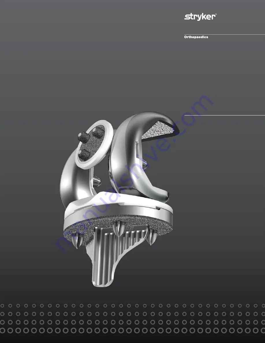
Tritanium
Surgical Protocol
with Triathlon Cementless Beaded PA Femoral Component
Page 1: ...Triathlon Tritanium Surgical Protocol with Triathlon Cementless Beaded PA Femoral Component ...
Page 2: ......
Page 3: ...al Resection 26 Step 3 Tibial Keel Punch 29 Patella Preparation 32 Trial Assessment 33 Tibial Preparation continued 34 Step 4 Tibial Peg Preparation 34 Femoral Implantation 38 Tibial Implantation 39 Tibial Insert Implantation 41 Patella Implantation 42 Product Dimensions 44 Catalog 45 Acknowledgments Stryker Orthopaedics wishes to thank the global Triathlon Tritanium Knee System Surgeon Advisors f...
Page 4: ...te function and stability Revision of previous unsuccessful knee replacement or other procedure Fracture of the distal femur and or proximal tibia that cannot be stabilized by standard fracture management techniques 2 The Triathlon Total Knee System beaded and beaded with Peri Apatite components are intended for uncemented use only The Triathlon Tritanium Tibial Baseplate and Tritanium Metal Backe...
Page 5: ...Surgical Protocol ...
Page 6: ...th cementless and cemented applications Surgeons may select an option based on preference and local bone conditions The Triathlon Tritanium baseplate is compatible with all available posterior stabilizing PS and cruciate retaining CR Triathlon femoral components for both cemented and cementless applications and accepts available Triathlon cruciate retaining CR condylar stabilizing CS and posterior...
Page 7: ...thylene Triathlon Tritanium Metal Backed Patella The Triathlon Tritanium Metal Backed Patella is indicated for both cemented and cementless applications The Triathlon Tritanium Metal Backed patellar components are available in symmetric and asymmetric configurations There are a total of 9 sizes which are compatible with all Triathlon femoral and tibial components The Triathlon Tritanium Metal Back...
Page 8: ...ment of the posterior cruciate ligament and slightly medial to the mid line of the distal femur Attach the 3 8 IM Drill to the Universal Driver and drill into the IM canal The first diameter will create a tight fit around the IM Rod If further clearance is desired continue to drill until the larger step diameter opens the hole Attach the T Handle Driver to the 5 16 IM Rod Insert the IM Rod into th...
Page 9: ...he trans epicondylar axis The guide should usually have contact with both medial and lateral trochlea for more stability Impact the distal captured pins in the Femoral Alignment Guide to aid in stabilization Note Impacting a distal capture pin that does not make contact with the femoral condyle may result in an undesirable change in the alignment guide position Pin the Distal Resection Guide to th...
Page 10: ...e block as described below to achieve a greater resection 2mm or 4mm Press the black button on the end of the Adjustment Block and pull to set the resection to the desired level Pin the Universal Resection Guide to the anterior femur Note If the medial O pin hole is too close to the edge of the bone on smaller femurs use the holes marked 2 which are closer to the center of the bone Please note thi...
Page 11: ...moral resection An optional Modular Capture may be attached to the Universal Resection Guide Squeeze the black tabs on the Modular Capture Distal Resection to insert into the Universal Resection Guide When using a modular capture a 050 1 25mm blade is used Remove the Modular Capture measure the resection and check the resection for flatness Remove the Universal Resection Guide Femoral Preparation ...
Page 12: ...e In the event of a hypoplastic femoral condyle Pin the Femoral Sizer through the EPI hole on the unaffected side for stability Rotate the Femoral Sizer and assess rotation using the rotational checks mentioned above Femoral Preparation Step 2 Femoral Sizing Femoral Preparation Hole for Pin to Reference Whiteside s Line EPI Line Indicator 10 Position the assembly flush on the resected distal femur...
Page 13: ...r size component will need to be chosen Ensure the femoral component chosen is compatible with the size of the tibial component selected during tibial preparation Once size confirmation is complete attach the 1 8 Peg Drill to the Universal Driver and create fixation pin holes for the 4 1 Cutting Block through the holes on the face of the Femoral Sizer marked EPI Femoral Preparation Figure 14 6541 ...
Page 14: ... Posterior and Chamfer Cuts Complete the remaining four femoral bone resections The use of a 050 1 25mm thick sawblade is recommended The order of bone resections is not critical however a recommended sequence for improved stability of the 4 1 Cutting Block is 1 Anterior cortex 2 Posterior condyles 3 Posterior chamfer 4 Anterior chamfer Note Cutting the anterior chamfer last helps stabilize the cu...
Page 15: ...ening with the intercondylar notch Optional surgical tip Use a CR Femoral Trial of the same size to identify the preferred M L position of the PS Box Cutting Guide Place the appropriate sized CR Femoral Trial on to the prepared femur Adjust the M L placement of the Femoral Trial to achieve the desired position of the femoral component Using a surgical marketing pen mark the location of the distal ...
Page 16: ... to continue the PS box preparation PS Box Preparation Option Chisel and Saw Option A Chisel and Saw Cut the cortical rim on both sides of the posterior most portion of the intercondylar notch using the oscillating saw Assemble the Box Chisel and insert into the slot Impact the Box Chisel with a mallet until seated to the stop Leave the Box Chisel in place to act as a reference plane Cut the media...
Page 17: ...sect the distal portion of the femur An oscillating or reciprocating saw can be used to resect the medial and lateral borders of the intercondylar notch to the proximal portion of the cutting guide Note After completion of options A or B the surgeon may choose to use the optional and recommended Triathlon PS Femoral Finishing Punch to complete preparation of the box Prior to trialing with a PS Fem...
Page 18: ... PS Box Cutting Guide until properly seated The Triathlon PS Femoral Box Finishing Punch is properly seated when the stop of the Finishing Punch is centered over the PS Box Cutting Guide drill holes See figure on left which depict the Triathlon PS Femoral Box Finishing Punch properly seated on the PS Box Cutting Guide When seated properly there should be a gap between the anterior nose of the Tria...
Page 19: ... Box Cutting Guide Place by hand not through impaction the appropriate size Triathlon PS Femoral Box Trial Protector into the prepared box to assure accuracy of the box preparation There are two Triathlon PS Femoral Box Trial Protectors Size 1 4 and Size 5 8 The box trial protector is fully seated when both the distal and posterior wings are flush with the bone Note Triathlon PS Femoral Box Trial ...
Page 20: ...Protector features a slot in which a retractor can be placed to lever against the distal femur during tibial subluxation If preferred select an extraction tool that fits into the retractor hole for ease of removal Remove the PS Femoral Box Trial Protector prior to assembling and implanting the Triathlon PS femoral component Figure 25 To avoid femoral component impingement and to improve flexion al...
Page 21: ...al is aligned with the distal plane Remove the Femoral Impactor Extractor and Impaction Handle and assess the fit of the PS or CR Femoral Trial Care must be taken to ensure that all of the osteophytes beyond the end of the posterior condyles are removed Femoral Preparation 6541 4 003 Headless Pins 3 6541 4 801 Universal Driver 6541 4 809 Headless Pin Driver 6541 4 810 Impaction Handle See Catalog ...
Page 22: ...bilized Knee If the Modular Femoral Distal Fixation Pegs are to be used the location holes may be prepared at this stage using the 1 4 Peg Drill attached to the Universal Driver The peg holes may also be prepared through the PS Box Cutting Guide Note Surgeon may leave Femoral Trial in place to protect the bone and aid with subluxing the tibia forward Figure 27 20 Femoral Preparation Step 5 Femoral...
Page 23: ... the Slap Hammer and remove the PS or CR Femoral Trial from the femur 6541 4 801 Universal Driver See Catalog CR Femoral Trial 6541 4 525 1 4 Peg Drill 6541 4 803 Slap Hammer Instrument Bar See Catalog PS Femoral Trial 6541 4 710 Posterior Osteophyte Removal Tool Femoral Preparation ...
Page 24: ...the Ankle Clamp the Distal Assembly the Tibial Alignment Proximal Rod and the Tibial Adjustment Housing These are assembled first Note The Tibial Adjustment Housing is available in 3º slope and 0º slope optional Tibial Slope Place the ankle clamp around the ankle and unlock the locking switch Tibial slope can be checked by verifying that the long axis of the assembly is parallel to the tibia Cauti...
Page 25: ...nt Ankle Clamp EM 6541 2 611 Tibial Alignment Proximal Rod EM 6541 2 610 Tibial Alignment Distal Assembly EM 6541 2 611E Express Proximal Rod EM Rotational Alignment Rotate the entire assembly to ensure that the base of the assembly is aligned with the center of the ankle The center of the ankle is generally in line with the second metatarsal Once alignment is confirmed set the bronze locking swit...
Page 26: ...into the canal beyond the isthmus to the physeal scar of the ankle if possible Rotational Alignment With the body of the Tibial Alignment Jig IM resting on the proximal tibia proper rotational alignment is achieved by rotating the instrument about the 5 16 IM Rod so that the vertical mounting bar is at the junction of the medial and middle 1 3rd of the tibial tubercle A Headless Pin or the 1 8 Dri...
Page 27: ...ly onto the mounting bar by pressing the bronze wheel on the Tibial Adjustment Housing Attach the Universal Alignment Handle to the Tibial Resection Guide and slide a Universal Alignment Rod through the handle for sagittal assessment When alignment is confirmed the Universal Alignment Handle should be centered over the ankle Tibial Preparation 0º slope 6541 2 704 3º slope 6541 2 705 Tibial Adjustm...
Page 28: ...he assembly up or down For fine adjustment turn the bronze wheel to the right to move the assembly up the Proximal Rod or turn left to move the assembly down the Proximal Rod Pin the Tibial Resection Guide in place Remove all alignment instruments leaving only the Tibial Resection Guide in place Note Rotate bronze wheel one extra turn to ensure stylus is under tension for accurate resection 26 Tib...
Page 29: ...on Note Ensure all excess debris bone and soft tissue is cleared from the Universal Tibial Template Do not impact the Tibial Insert Trial Tibial Preparation 6541 2 611E Express Proximal Rod EM 0º slope 6541 2 704 3º slope 6541 2 705 Tibial Adjustment Housing Right 6541 2 700 Left 6541 2 701 Tibial Resection Guide 6541 2 611 Tibial Alignment Proximal Rod EM 6541 4 806 Universal Alignment Handle 654...
Page 30: ... border of the Universal Tibial Template Remove the PS or CR Femoral Trial and disassemble the Tibial Trial Insert from the Universal Tibial Template Check the orientation and coverage of the Universal Tibial Template on the proximal tibia again while referencing the marks on the anterior border of the Universal Tibial Template and the anterior cortex made previously Reposition the Universal Tibia...
Page 31: ...terior portion of the Universal Tibial Template Allow the Keel Punch Guide to sit flat on the Universal Tibial Template and push forward on the handle to lock the Keel Punch Guide to the Universal Tibial Template Tibial Preparation Lock Tibial Preparation Step 3 Tibial Keel Punch See Catalog Universal Tibial Template 6541 4 003 Headless Pins 3 Size 1 2 3 6541 2 713 Size 4 5 6 7 8 6541 2 748 Keel P...
Page 32: ...unch Guide Use a mallet to impact the Keel Punch Tip The presence of variably dense bone in the proximal tibia can influence the advancement of the Keel Punch Take care to ascertain that the pinned Universal Tibial Template maintains its position during Keel Punch impaction It may be advisable to remove sclerotic bone in the path of the Keel Punch prior to impaction ...
Page 33: ...nch Guide handle and pull the handle to cantilever the Keel Punch out of the tibia Tibial Preparation See Catalog Universal Tibial Template 6541 4 003 Headless Pins 3 Size 1 2 3 6541 2 713 Size 4 5 6 7 8 6541 2 748 Keel Punch Guide 6541 4 804 Headless Pin Extractor See Catalog Cementless Keel Punch ...
Page 34: ... is optional and is based on surgeon preference and surgeon evaluation of the articulating surface Remove all osteophytes and synovial insertions around the patella and measure thickness using a caliper After determining the depth of the cut affix the stylus in the appropriate slot of the Patella Resection Guide and capture the patella between the jaws of the guide Note Care should be taken when d...
Page 35: ...esection Guide Figure 46 Instrument Bar 33 Patella Preparation Remove any residual cartilage and wash away all debris Place correct size Patella Trial Symmetric or Asymmetric onto the prepared patella Replace all Trials and assess patellar tracking by taking the knee through a ROM The patella should track normally throughout the ROM without tendency for tilting or lateral subluxation Trial Assessm...
Page 36: ...rill Template that corresponds to the pre determined Tibial Baseplate size The position of the four holes and the keel on the underside of the Tibial Peg Drill Template correspond to the relative location of the keel and four pegs on the implant Insert the keel on the Tibial Peg Drill Template into the prepared keel slot as shown Ensure that the Tibial Peg Drill Template sits flush against the res...
Page 37: ... template holes using the 1 8 Tibial Peg Drill taking care to ensure surgical glove and fingers are not in contact with drill prior to drilling Drilling is complete when the drill stop has contacted the template surface Carefully remove the Tibial Peg Drill Template from the bone by lifting straight up and out of keel slot Tip The central hole of the Tibial Drill Guide can be used to facilitate re...
Page 38: ...Figure 52 36 Tibial Preparation Step 4 Tibial Peg Preparation continued Tibial Preparation Image of the Tibia After Tibial Preparation ...
Page 39: ...rill taking care to ensure surgical glove and fingers are not in contact with drill prior to drilling Ensure axial alignment before drilling Drilling is complete after the drill stop has contacted bone Do not continue to drive the drill after the stop has been reached Note Ensure Tibial Peg Drill template is removed prior to drilling with the 7 32 Tibial Peg Drill Tibial Preparation Step 4 Tibial ...
Page 40: ...it until fully seated Posterior Stabilized Knee If Modular Femoral Distal Fixation Pegs are to be used assemble the pegs to the Femoral Component using the 1 8 Hex Drive and the Slip Torque Handle prior to implantation The Femoral Impactor can be attached to the Impaction Handle to further seat the Femoral Component onto the prepared femur 38 Femoral Implantation Component Implantation ...
Page 41: ...te with or without cement If Cementless Connect the Tibial Baseplate Impactor Extractor to the Impaction Handle Connect the Tibial Baseplate Impactor Extractor to the Triathlon Tritanium Baseplate over the Impactor Pad and lock the lever The Triathlon Tritanium Tibial Baseplate is packaged together with an Impactor Pad as shown Impactor Pad 5536 B X00 Baseplate See Catalog 6541 4 901 Impactor Pad ...
Page 42: ...eplate Discard the Impactor Pad Caution It is recommended that the Impacter Pad be left on during impaction Discard the Impactor Pad following impaction of the baseplate and prior to the Tibial Insert Implantation step Do not implant the Impactor Pad Note Do not rock the baseplate in the bone because it could affect the press fit If Cementing If a decision is made to cement the Triathlon Tritanium...
Page 43: ...oint and angle the insert posteriorly into the Triathlon Tritanium Baseplate The posterior lip of the Tibial Insert must fit beneath the lip on the posterior Triathlon Tritanium Baseplate wall Attach the Tibial Insert Impactor to the Impaction Handle and impact to snap the Insert in place anteriorly The Tibial Insert is fully seated once the locking wire locks under the barbs on the anterior inter...
Page 44: ...gs of the Patellar Component to the fixation peg holes previously prepared Caution When using an asymmetric patellar component ensure that the lateral extension of the asymmetric patella implant is over the lateral facet of the native patella Lightly press the patellar pegs into the native patella Implanting the patellar component using the Patella Inserter Hold the native patella patella implant ...
Page 45: ...ompressing the implant and native patella Unscrew the T handle and remove the Patella Inserter and Capture Re examine to ensure the the implant is properly seated on the native patella If cementing the patella component If a decision is made to cement the Tritanium Metal Backed Patella or to use an All Poly Patella the peg holes must be prepared with the All Poly Patella Drill 6541 3 524 If necess...
Page 46: ... 5536 B 300 3 44 67 28 40 9 7 5536 B 400 4 46 70 28 52 9 7 5536 B 500 5 49 74 28 52 9 7 5536 B 600 6 52 77 28 52 11 7 5536 B 700 7 56 80 28 58 11 7 5536 B 800 8 60 85 28 58 12 7 Part No Size Diameter mm Thickness mm 5556 L 319 S31 31 9 5556 L 339 S33 33 9 5556 L 360 S36 36 10 5556 L 391 S39 39 11 Part No Size S I Diameter mm M L Width mm Thickness mm 5552 L 299 A29 29 33 9 5552 L 320 A32 32 36 10 ...
Page 47: ...09 Box Chisel 1 6541 4 710 Posterior Osteophyte Removal Tool Optional 1 6541 4 800 T Handle Driver 1 6541 4 801 Universal Driver 1 6541 4 802 1 8 Hex Drive Optional 1 6541 4 803 Slap Hammer 1 6541 4 804 Headless Pin Extractor 1 6541 4 805 Tibial Baseplate Impactor Extractor 1 6541 4 806 Universal Alignment Handle 1 6541 4 807 Femoral Impactor Extractor 1 6541 4 809 Headless Pin Driver 1 6541 4 810...
Page 48: ... x 9mm 1 5550 T 339 Symmetric Patella 33mm x 9mm 1 5550 T 360 Symmetric Patella 36mm x 10mm 1 5550 T 391 Symmetric Patella 39mm x 11mm 1 5551 T 299 Asymmetric Patella 29mm S I x 33mm M L x 9mm 1 5551 T 320 Asymmetric Patella 32mm S I x 36mm M L x 10mm 1 5551 T 350 Asymmetric Patella 35mm S I x 39mm M L x 10mm 1 5551 T 381 Asymmetric Patella 38mm S I x 42mm M L x 11mm 1 5551 T 401 Asymmetric Patell...
Page 49: ...3 Triathlon Cementless Keel Punch 1 3 1 Each Size 6541 6 046 Triathlon Cementless Keel Punch 4 6 1 Each Size 6541 6 078 Triathlon Cementless Keel Punch 7 8 1 Each Size 6541 8 100 Triathlon Tritanium Prep Tray 1 6541 2 64X Tritanium Tibial Peg Drill Template X 1 2 3 4 5 6 7 and 8 1 Each Size 6541 2 625 Tritanium Tibial Peg Drill 1 8 1 6541 2 626 Tritanium Tibial Peg Drill 7 32 1 Catalog Description...
Page 50: ...Universal Tibial Template 1 6541 2 604 4 Universal Tibial Template 1 6541 2 605 5 Universal Tibial Template 1 6541 2 606 6 Universal Tibial Template 1 6541 2 609 Tibial Alignment Ankle Clamp EM 1 6541 2 610 Tibial Alignment Distal Assembly EM 1 6541 2 611E Express Proximal Rod EM 1 6541 2 620 Tibial Template Converter 1 6541 2 700 Tibial Resection Guide Right 1 6541 2 701 Tibial Resection Guide Le...
Page 51: ...2 T 411A PS Tibial Insert Trial 4 11mm 1 5532 T 413A PS Tibial Insert Trial 4 13mm 1 5532 T 416A PS Tibial Insert Trial 4 16mm 1 5532 T 419A PS Tibial Insert Trial 4 19mm 1 5532 T 509A PS Tibial Insert Trial 5 9mm 1 5532 T 511A PS Tibial Insert Trial 5 11mm 1 5532 T 513A PS Tibial Insert Trial 5 13mm 1 5532 T 516A PS Tibial Insert Trial 5 16mm 1 5532 T 519A PS Tibial Insert Trial 5 19mm 1 5532 T 6...
Page 52: ... 319A CR Tibial Insert Trial 3 19mm 1 5530 T 409A CR Tibial Insert Trial 4 9mm 1 5530 T 411A CR Tibial Insert Trial 4 11mm 1 5530 T 413A CR Tibial Insert Trial 4 13mm 1 5530 T 416A CR Tibial Insert Trial 4 16mm 1 5530 T 419A CR Tibial Insert Trial 4 19mm 1 5530 T 509A CR Tibial Insert Trial 5 9mm 1 5530 T 511A CR Tibial Insert Trial 5 11mm 1 5530 T 513A CR Tibial Insert Trial 5 13mm 1 5530 T 516A ...
Page 53: ...32 T 116A PS Tibial Insert Trial 1 16mm 1 5532 T 119A PS Tibial Insert Trial 1 19mm 1 5532 T 809A PS Tibial Insert Trial 8 9mm 1 5532 T 811A PS Tibial Insert Trial 8 11mm 1 5532 T 813A PS Tibial Insert Trial 8 13mm 1 5532 T 816A PS Tibial Insert Trial 8 16mm 1 5532 T 819A PS Tibial Insert Trial 8 19mm 1 6541 5 711 1 MIS PS Box Cutting Guide 1 6541 5 718 8 MIS PS Box Cutting Guide 1 6541 2 078 Size...
Page 54: ... Tibial Template 1 6541 8 112 Triathlon 1 8 CR Lower Tray 1 6541 9 000 Triathlon Case 1 5511 T 201 PS Femoral Trial 2 Left 1 5511 T 202 PS Femoral Trial 2 Right 1 5511 T 701 PS Femoral Trial 7 Left 1 5511 T 702 PS Femoral Trial 7 Right 1 5532 T 209A PS Tibial Insert Trial 2 9mm 1 5532 T 211A PS Tibial Insert Trial 2 11mm 1 5532 T 213A PS Tibial Insert Trial 2 13mm 1 5532 T 216A PS Tibial Insert Tr...
Page 55: ...PS Tibial Insert Trial 8 22mm 1 5532 T 825A PS Tibial Insert Trial 8 25mm 1 6541 8 120 Triathlon 1 8 Max PS Upper Tray 1 6541 9 000 Triathlon Case 1 5510 T 201 CR Femoral Trial 2 Left 1 5510 T 202 CR Femoral Trial 2 Right 1 5510 T 701 CR Femoral Trial 7 Left 1 5510 T 702 CR Femoral Trial 7 Right 1 5530 T 209A CR Tibial Insert Trial 2 9mm 1 5530 T 211A CR Tibial Insert Trial 2 11mm 1 5530 T 213A CR...
Page 56: ...ach Size 5530 T X19A CR Modified Hollow Tibial Insert Trial 19mm X 1 2 3 4 5 6 7 and 8 1 Each Size 5532 T X09A PS Modified Hollow Tibial Insert Trial 9mm X 1 2 3 4 5 6 7 and 8 1 Each Size 5532 T X11A PS Modified Hollow Tibial Insert Trial 11mm X 1 2 3 4 5 6 7 and 8 1 Each Size 5532 T X13A PS Modified Hollow Tibial Insert Trial 13mm X 1 2 3 4 5 6 7 and 8 1 Each Size 5532 T X16A PS Modified Hollow T...
Page 57: ...n CR Femoral Component Left Cementless Beaded w PA X 1 2 3 4 5 6 7 and 8 1 Each Size 5517 F X02 Triathlon CR Femoral Component Right Cementless Beaded w PA X 1 2 3 4 5 6 7 and 8 1 Each Size 5515 F X01 Triathlon PS Femoral Component Left Cemented X 1 2 3 4 5 6 7 and 8 1 Each Size 5515 F X02 Triathlon PS Femoral Component Right Cemented X 1 2 3 4 5 6 7 and 8 1 Each Size 5514 F X01 Triathlon PS Femor...
Page 58: ... P X16 Triathlon CR Tibial Insert Conventional Polyethylene 16mm X 1 2 3 4 5 6 7 and 8 1 Each Size 5530 P X19 Triathlon CR Tibial Insert Conventional Polyethylene 19mm X 1 2 3 4 5 6 7 and 8 1 Each Size X3 Inserts 5530 G X09 Triathlon CR Tibial Insert X3 9mm X 1 2 3 4 5 6 7 and 8 1 Each Size 5530 G X11 Triathlon CR Tibial Insert X3 11mm X 1 2 3 4 5 6 7 and 8 1 Each Size 5530 G X13 Triathlon CR Tibi...
Page 59: ...rt X3 19mm X 1 2 3 4 5 6 7 and 8 1 Each Size 5531 G X22 Triathlon CS Tibial Insert X3 22mm X 1 2 3 4 5 6 7 and 8 1 Each Size 5531 G X25 Triathlon CS Tibial Insert X3 25mm X 1 2 3 4 5 6 7 and 8 1 Each Size Conventional Polyethylene Inserts 5532 P X09 Triathlon PS Tibial Insert Conventional Polyethylene 9mm X 1 2 3 4 5 6 7 and 8 1 Each Size 5532 P X11 Triathlon PS Tibial Insert Conventional Polyethy...
Page 60: ...nium S33mm x 9mm 1 5556 L 360 Symmetric Patella with Tritanium S36mm x 10mm 1 5556 L 391 Symmetric Patella with Tritanium S39mm x 11mm 1 Catalog Description Sizes Qty Conventional Polyethylene Patellas 5551 L 299 Asymmetric Patella Conventional Polyethylene A29mm S I x 9mm 1 5551 L 320 Asymmetric Patella Conventional Polyethylene A32mm S I x 10mm 1 5551 L 350 Asymmetric Patella Conventional Polyet...
Page 61: ...th Peri Apatite A40mm S I x 11mm 1 S I Superior Inferior Modular Femoral Distal Fixation Peg Part Number 5575 X 000 Modular Femoral Distal Fixation Peg 2 per pack Catalog Description 6541 5 212 Sizes 1 2 Triathlon PS Femoral Finishing Punch 6541 5 234 Sizes 3 4 Triathlon PS Femoral Finishing Punch 6541 5 256 Sizes 5 6 Triathlon PS Femoral Finishing Punch 6541 5 278 Sizes 7 8 Triathlon PS Femoral F...
Page 62: ...60 Notes Triathlon Tritanium Surgical Protocol with Triathlon Cementless Beaded PA Femoral Component ...
Page 63: ...61 Notes Triathlon Tritanium Surgical Protocol with Triathlon Cementless Beaded PA Femoral Component ...
Page 64: ...Notes Triathlon Tritanium Surgical Protocol with Triathlon Cementless Beaded PA Femoral Component ...
Page 65: ... 4 4 4 Patella Type Femoral Components Asymmetric Asymmetric Metal Backed Symmetric Metal Backed Symmetric CR Cemented PS Cemented TS Cemented Cementless CR Beaded PS Beaded CR Beaded with PA PS Beaded with PA 4 4 4 4 4 4 4 4 4 4 4 4 4 4 4 4 4 4 4 4 4 4 4 4 4 4 4 4 Insert Type Tibial Baseplates CR CS PS TS Cemented Cruciform No Cemented Universal Cementless Beaded Cruciform No Beaded Screw Fix No ...
Page 66: ...el and or instructions for use before using any Stryker product The products depicted are CE marked according to the Medical Device Directive 93 42 EEC Products may not be available in all markets because product availability is subject to the regulatory and or medical practices in individual markets Please contact your Stryker representative if you have questions about the availability of Stryker...