background image

25

&OHMJTI

6.8. DISEQC 1.2 SETUP MENU

DiSEqC 1.2 Setup Menu is located under Antenna

Installation Menu. User selects the name of the satellite

and its properties like polarisation and frequency band at

the Antenna Installation Menu before entering DiSEqC 1.2

Setup Menu.
Setting “Polarisation” and “22 kHz” parameters from

Antenna Installation Menu is optional. By default,

polarisation is set to “H/V” (both horizontal and vertical

frequencies) and 22 kHz is set to “Auto” (both 22 kHz Off

and 22 kHz On). These parameters can be left in their

default positions to simplify the installation task. The aim

is to drive the motor on the polar axis and watch the signal

quality indicator. When the receiver is tuned to a satellite,

the signal quality bar will rise. If the user is satisfied with

the signal quality he stores the current position of the

antenna. Otherwise he will try to fine-tune it until the desired

level is reached.

There are a certain number of satellites, which have

predefined presets stored in the box. Satellites having

predefined presets appear with their original names like

Astra, Hotbird, etc. If a satellite has predefined presets, the

user does not have to enter a reference transponder from

that specific satellite although It is possible to enter a

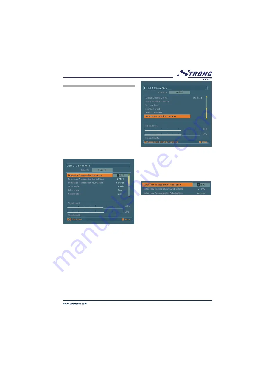
reference transponder for all satellites. Figure shows the

upper part of the DiSEqC 1.2 Setup Menu
Satellites that do not have predefined presets appear with

names like User 1, User 2, etc. Here, frequency, symbol

rate and polarisation of a reference transponder should be

entered in order to be tuned into the satellite.

The two essential parameters, frequency and polarisation

of a reference transponder should be entered according to

the antenna settings (See Figure 6.8.3). If the polarisation

setting is vertical in Antenna Installation Menu, it will be

vertical in DiSEqC 1.2 Setup Menu automatically and the

user will not be able to change it. Same situation is valid

when the polarisation is horizontal.

Polarisation should be set to “H/V” from Antenna

Installation Menu in order to be able to changed by the user

from DiSEqC 1.2 Setup Menu.  Frequency values should

also be entered according to the 22KHz mode. In “22 kHz

Off” mode (Low Band), the frequency range is between

10700 and 11900. It is between 11550 and 12750 for “22

kHz On” (High Band). If 22 kHz mode is set to “Auto”, the

user can enter a value in the whole range that is between

10700 and 12750.  Any frequency value out of the specified

range will cause a warning message to appear on the

screen.
The following part gives a detailed explanation about the

DiSEqC 1.2 motor functions.

All manuals and user guides at all-guides.com

Summary of Contents for SRT 4120

Page 1: ...Y SETTINGS 16 6 5 SYSTEM SET UP MENU 17 6 5 1 MENU LANGUAGE 17 6 5 2 AUDIO LANGUAGE 17 6 5 3 SUBTITLE LANGUAGE 17 6 5 4 TV TYPE 17 6 5 5 TV OUT 17 6 5 6 PARENTAL SETTINGS 18 6 5 6 1 CHILD LOCK 18 6 5 6 2 MENU LOCK 18 6 5 6 3 CHANGE PIN 18 6 5 7 DATE TIME SETTINGS 18 6 5 7 1 TIME 18 6 5 7 2 DATE 19 6 5 7 3 OFFSET UTC H 19 6 5 8 ADVANCED BASIC MENU 19 6 5 9 RECEIVER UPGRADE 20 6 6 TIMER MENU 20 6 7 ...

Page 2: ... or right Multi language audio support up to 25 Teletext function support VBI reinsertion Software update via scart Reset to factory settings function Loop through VPS signal for VCR recordings in Standby mode C and Ku Band reception LNB Control Horizontal Vertical polarity switching 18 13V 7 5 0 22 kHz switching toneburst A B switching for dish selection DiSEqC 1 0 Pre installed FTA channels for ...

Page 3: ...Video Decoding MP ML PAL NTSC 4 3 16 9 Video Out PAL Audio Decoding MPEG Layer I II 32 44 1 48 KHz sampling frequencies single dual channels stereo joint stereo System switching TV RADIO Last watched channel saving LNB short circuit and overload protection by software IR remote control Less than 7W power consumption in standby mode All manuals and user guides at all guides com ...

Page 4: ...eceiver shall not be exposed to dripping or splashing and no objects filled with liquids such as vases shall be placed on the apparatus 2 4 SMALL OBJECTS Coins or other small objects must be kept away from the receiver as they can fall through the ventilation slots of the receiver and cause serious damage 2 5 CLEANING Disconnect the receiver from the wall socket before cleaning it Use a dry cloth ...

Page 5: ...ons Take care to provide good air circulation Place the receiver in a location with adequate ventilation to prevent heating up of the receiver No naked flame sources such as lighted candles should be placed on the apparatus Never stack other electronic equipment on top of the receiver Remove batteries from remote control when it is not to be used for a long period Otherwise it can be damaged due t...

Page 6: ...ch does not have RGB input you will not achieve the high performance of your digital set top box since your TV will use composite video signal instead of the RGB signals See Diagram 1 Page 35 3 3 2 CONNECTION TO SATTELLITE ANTENNA Carefully plug in the connectors of the satellite antenna cables to the terminal of your set top box labeled as LNB See Diagram 1 Page 35 3 3 3 VCR SCART CONNECTION 1 Co...

Page 7: ...G 5 QIUD 5HG 4120 JLWDO 6DWHOOLWH 5HFHLYHU L BACK PANEL 79 6 57 VRFNHW 9 5 6 57 VRFNHW LJLWDO XGLR 2XWSXW 6 3 9 5 79 9 a 8 2 5 6 7 1 6 3 6XSSOLHG E 6WURQJ R DSDQ HIW 5LJKW QDORJ XGLR 2XWSXW 6 7 1 QWHQQD 1 3RZHU RUG All manuals and user guides at all guides com ...

Page 8: ...8 OHMJTI 5 REMOTE CONTROL 0 18 012 345 678 9 9 79 5 2 3 3 9 9 67 9 68 7 7 8 1 0 2 All manuals and user guides at all guides com ...

Page 9: ...RSOR LEFT V 9 OK 10 FAVOURITE PROGRAM BLUE BUTTON 11 AUDIO MODE SELECTION YELLOW BUTTON 12 INFO HELP 13 LANGUAGE SELECTION LANG 14 GUIDE EPG MENU 15 PROGRAM LIST PAGE UP RED BUTTON 16 SUBTITLE PAGE DOWN GREEN BUTTON 17 MUTE 18 AV 19 PROGRAM UP P 20 PROGRAM DOWN P 21 VOLUME UP V 22 VOLUME DOWN V All manuals and user guides at all guides com ...

Page 10: ...ntrol or on the front panel a banner is displayed which shows graphically the present volume The sound is increased or decreased by moving the cursor on volume scale by pressing V and V keys respectively 5 7 LIST PAGE UP RED BUTTON When the LIST key is pressed whole channel list or one of 4 favourite lists is displayed If the last watched listened channel is one of the favourite channels then the ...

Page 11: ...is activated FAV button toggles between the favourites The limit for the number of favourite channels is 100 In no menu mode pressing FAV blue button on remote control will cause the receiver to change the current channel to the first favourite channel The user can select any channel in current favourite list by toggling pressing and keys and other favourite lists by pressing FAV button again If t...

Page 12: ...rameters as explained in theAntenna Installation Menu go to the Start Scan line and press OK Then choose Yes for Start Scan The box will automatically find the preset channels and store them 6 2 MAIN MENU Main menu is accessed pressing the MENU key on the remote control The items accessed through the main menu are Channel Table Installation System Set up Timers 6 3 CHANNEL ORGANISER Following oper...

Page 13: ...ous next character keys toggles the current character i e b character becomes cwith and a with The numeric buttons from 0 to 9 replaces the highlighted character with the character that corresponds to selected numeric The limit for the channel name is 15 character In this editing mode pressing Menu cancels the editing and pressing OK saves the new name of the channel 6 3 5 ADDING LOCKS TO CHANNELS...

Page 14: ... etc and 5 user defined satellites as User1 User5 append to them The satellites can be renamed by remote control Low Frequency You should set this value according to low oscillator frequency of your LNB device by default 9750 for Universal LNB High Frequency You should set this value according to high oscillator frequency of your LNB device by default 10600 for Universal LNB Polarisation You can s...

Page 15: ... Antenna Installation Menu is displayed and the user selects the satellite name and other specifications to find out channels After pressing Start Scan the values entered are stored to that satellite And the user will be asked whether he would like to start scan or not By pressing OK all channels predetermined in database of that satellite will be searched and stored into receiver and channel tabl...

Page 16: ... Quality bar shows lock quality of the device for entered values If Network Search item selected as YES the parameters of all transponders will be collected from NIT Network Information Table and the tuning will be performed When tuning in the screen there will be shown the satellite name and frequency polarization symbol rate of the current transponder under the found programs As shown below ther...

Page 17: ...rrent menu language can be changed and updated by keys 6 5 2 AUDIO LANGUAGE By pressing keys Audio Language option is highlighted The current audio language can be changed and updated by keys Changes will be updated whileexitingSystemSet upMenu Whennewchannelsare added they are recorded with the default audio language in database 6 5 3 SUBTITLE LANGUAGE By pressing keys Subtitle Language option is...

Page 18: ...option After pressing OK button new password menu is displayed New password is entered using 0 1 2 9 keys The new password must be confirmed for security If both passwords are four digits long and the same password is changed It is updated after exiting Parental Settings Menu If you forget the password you can enter locked channels and menus and change password by using the universal password 8277...

Page 19: ...tion is highlighted and time offset can be toggled with keys Time offset will be changed just after the offset is toggled Time will be also updated according to the new time offset By pressing MENU key to return System Set up Menu time and offset UTC h is updated 6 5 8 ADVANCED BASIC MENU By pressing keys Basic Menu Advanced Menu option is highlighted and by pressing OK if the advanced menu is act...

Page 20: ...ls are as follows Type By using keys channel type i e TV or Radio is selected Name According to the type that is chosen above keys will navigate the user through the TV or Radio list and name of the channel is selected Start By using 0 1 2 9 keys start time of the timer is entered End By using 0 1 2 9 keys end time of the timer is entered Date By using 0 1 2 9 keys date of the timer is entered Mod...

Page 21: ...rent event information is displayed in the event box Red Green buttons can be used to scroll up down Yellow Blue buttons can be used to read the information line by line At the right bottom of the screen current and next event duration are displayed on an 3 hour time scale The highlighted part yellow is for the current event 6 7 1 2 NEXT EVENT MODE By pressing OK keys watched listened highlightedc...

Page 22: ...tton and the box is in TV mode then keys will switch to the next previous channel in the TV Favourite 1 list If Favourite1 is chosen with the Blue button and the box is in Radio mode then keys will switch to the next previous channel in the Radio Favourite 1 list 6 7 3 2 NUMBER KEYS Pressing a number key will activate a small digit entry window on the left upper corner of the screen in no menu mod...

Page 23: ...er is displayed which shows the present volume level graphically By keeping these keys pressed the sound can be increased with 4 key or decreased with 3 key When the Mute key is pressed mute symbol is displayed on the upper right side of the screen The mute symbol will stay until mute is pressed again or V V pressed Unless there is a menu display the mute symbol will always be on the screen 6 7 5 ...

Page 24: ... which includes favourite channels appears To delete a channel highlight it using or Red Green buttons then highlight the Delete button using keys and press OK A message appears to confirm your decision if you still want to delete then select YES and press OK once deleting operation will be cancelled if NO is selected or by pressing Menu key Please note that if the current list is a favourite list...

Page 25: ...lite although It is possible to enter a reference transponder for all satellites Figure shows the upper part of the DiSEqC 1 2 Setup Menu Satellites that do not have predefined presets appear with names like User 1 User 2 etc Here frequency symbol rate and polarisation of a reference transponder should be entered in order to be tuned into the satellite The two essential parameters frequency and po...

Page 26: ...mes handy when fine tuning is needed 6 8 4 SET EAST LIMIT Stores the current location of the positioner as the east limit 6 8 5 SET WEST LIMIT Stores the current location of the positioner as the west limit 6 8 6 ENABLE DISABLE LIMITS Enabling the software limits will cause the motor not to drive after east or west limit is reached When the software limits are disabled the positioner motor will dr...

Page 27: ...Hypertrm exe file 5 Give a name and choose an icon for the connection You do not need to make a new connection every time You can use this name for the future connections 6 Choose communication port in the new coming window COM1 or COM2 whichever you have used in Step 1 7 Port settings should be as follows Bits per second 115200 Data Bits 8 Parity None Stop bits 1 Flow control None 8 Now Hyper Ter...

Page 28: ...ll start if the Search for New Version button is pressed Or you can exit by pressing menu After pressing the Search for New Version button the STB starts the search procedure and will check if the broadcasted software is newer than its own version Since this process takes some time a warning message is displayed If there is no new software No new software found Press OK to exit message will be sho...

Page 29: ...fter loading the software into memory SDRAM it will be written permanent memory flash If STB power is cut while the downloaded software is being written into the flash memory then the new software will not run since it will not be written completely into permanent memory The receiver has backup system software that can be restored in such cases The restoring process is triggered when the STB is sw...

Page 30: ... going to standby going to standby The remote control is not working The digital set top box is in standby Press the standby key check if nothing blocks the front panel Remote control is incorrectly aimed Change the batteries Battery exhausted You see the on screen error message The dish installation is not correct Check the connections related with LNB short circuit or cable connections have been...

Page 31: ...Transmission Standards DVB MPEG2 i DEMODULATION QPSK with SYMBOL RATE from 2 Msps to 45 Msps FEC for all DVB Modes Automatically found ii VIDEO All MPEG2 MP ML formats with up conversion and filtering to CCIR601 format Aspect Ratio 4 3 16 9 with pan vector iii AUDIO MPEG1 Layer 1 and 2 Sampling frequencies supported are 32 44 1 48 kHz Output can be programmed as STEREO LEFT only or RIGHT only on b...

Page 32: ...ctor 2 x RCA R L Output 0 5 Vrms Z 1 kW 8 7 DIGITAL AUDIO Connector 1 x RCA Output Digital S PDIF Output 0 5 V 8 8 A V DATA IN OUT Scart TV scart VCR scart RGB Video Output TV scart CVBS Video Output TV scart VCR scart CVBS Video Input VCR scart AnalogAudio Output TV scart RCA jack VCR scart AnalogAudio Input VCR scart DigitalAudio Output RCA jack Data Interface RS 232 integrated into TV SCART Bau...

Page 33: ... 7 5 3 1 Video output Composite video signal 1 Vp p 3dB 75W Video input Composite video signal 1 Vp p 3dB 75W for VCR Audio output 0 5 Vrms Z 1kW Audio input 0 5 Vrms Z 10kW for VCR Function switching 12V 6V for 4 3 16 9 Z 10kW All manuals and user guides at all guides com ...

Page 34: ...XWSXW DVW ODQNLQJ 2XWSXW 1 1 9 6 2XWSXW 1R RQQHFWLRQ 1 3 1 6 1 3 1 6 1 8 11 VCR SCART SOCKET XGLR 5LJKW 2XWSXW XGLR 5LJKW QSXW XGLR HIW 2XWSXW 1 1 XGLR HIW QSXW 1R RQQHFWLRQ XQFWLRQ 6ZLWFKLQJ QSXW 1 1R RQQHFWLRQ 1R RQQHFWLRQ 1R RQQHFWLRQ 1 1 1R RQQHFWLRQ 1R RQQHFWLRQ 1 1 9 6 2XWSXW 9 6 QSXW 1 3 1 6 1 3 1 6 1 All manuals and user guides at all guides com ...

Page 35: ... 7 1 6 3 9 a 6XSSOLHG E 6WURQJ R DSDQ TV LJLWDO 9 5HFHLYHU 9 PSOLILHU X L6 T 6ZLWFK LVK LVK Diagram 2 LJLWDO 9 5HFHLYHU 9 PSOLILHU 79 9 5 8 2 5 9 5 79 6 7 1 6 3 9 a 6XSSOLHG E 6WURQJ R DSDQ X L6 T 6ZLWFK LVK LVK All manuals and user guides at all guides com ...

Reviews: