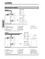
System Supply
System Return
EAF
EAF
UAC
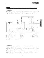
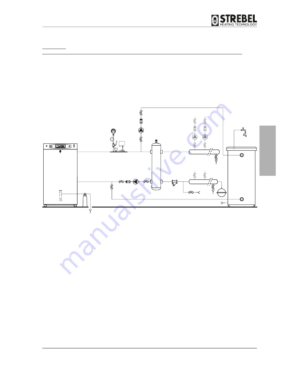
Example 3:
System for the heating and production of DHW with storage tank upline of hydraulic separator
1 Heating unit
2 Condensate drain syphon
3 Condensate neutraliser (*)
4 Drain
5 ISPESL safety module
6 Primary pump 2
b
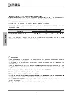
WARNINGS
•
Fill the condensate drain syphon (2) to a sufficient level and route the condensate drain hose correctly. Envisage suitable
condensate treatment systems.
•
The safety valve drain must be connected to a suitable disposal system. The manufacturer is not responsible for
possible flooding caused by intervention of the safety valve.
•
Systems charged with anti-freeze require the compulsory use of water shut-off devices.
•
The selection and installation of the system components is the task of the installer, who must observe all current
legislation and professional technical practices.
•
The expansion vessel of the heating circuit must ensure total absorption of the fluid expansion in the system.
b
WARNINGS
•
If the DHW is produced by the storage tank pump located upline of the hydraulic separator, use boiler pump 2 as the
primary pump (without the mix valve).
This enables management of two above pumps, to avoid increases in the temperature of the heating circuit.
7 Hydraulic separator
8 Screening filter
9 Shut-off valve
10 Supply manifold
11 Return manifold
12 Check valve
13 Expansion vessel
14 Remote storage tank
15 Storage tank pump
EAF Cold water inlet
UAC Domestic water utility
1
10
15
12
11
14
13
6
9
9
9
9
9
9
9
9
9
7
8
5
4
4
3
2
(*) Not supplied with heating unit. Available as accessory.
- 21
-
INST
ALLA
TION
Summary of Contents for S-AF
Page 63: ...NOTES 63 ...

