
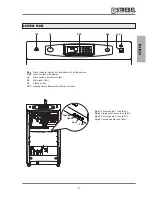
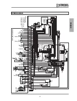

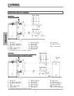
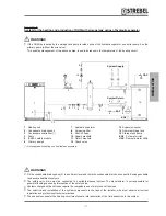
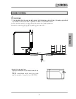
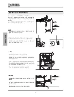
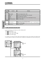
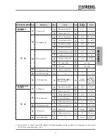

OPERATING PRINCIPLE DIAGRAMS
System Return
EAF
System Supply
System Return
EAF
UAC
System Supply
EAF
(*) Not supplied with heating unit. Available as accessory.
(*) Not supplied with heating unit. Available as accessory.
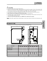
Example 1:
Heating-only system
Example 2:
System for the heating and production of DHW with
storage tank downline of hydraulic separator
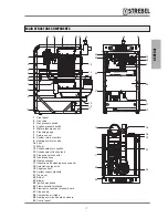
1 Heating unit
2 Condensate drain syphon
3 Condensate neutraliser (*)
4 Drain
5 ISPESL safety module
6 Primary pump 1
1 Heating unit
2 Condensate drain syphon
3 Condensate neutraliser (*)
4 Drain
5 ISPESL safety module
6 Primary pump 1
7 Hydraulic separator
8 Screening filter
9 Shut-off valve
10 Supply manifold
11 Return manifold
12 System pump
7 Hydraulic separator
8 Screening filter
9 Shut-off valve
10 Supply manifold
11 Return manifold
12 System pump
13 Check valve
14 Expansion vessel
EAF Cold water inlet
13 Check valve
14 Expansion vessel
15 Remote storage tank
16 Storage tank pump
EAF Cold water inlet
UAC Domestic water utility
1
1
10
10
12
12
16
13
13
11
11
14
14
6
6
9
9
9
9
9
9
9
9
9
9
9
9
9
9
7
7
8
8
5
5
4
4
4
4
3
2
3
2
- 20
-
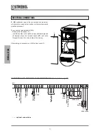
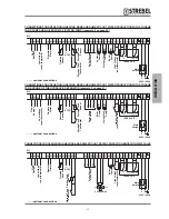
INST
ALLA
TION
Summary of Contents for S-AF
Page 63: ...NOTES 63 ...


