


( 1 :30 )
1
1
2
2
3
3
4
4
5
5
6
6
A
A
B
B
C
C
D
D
Status
Änderungen
Datum
Name
Datum
Name
Gezeichnet
Kontrolliert
Norm
Maßstab:
Diese Zeichnung darf ohne unsere
Genehmigung weder vervielfältigt
noch Dritten oder Konkurrenzfirmen
zugängig gemacht werden.
Allgemein-
tolleranzen
ISO 2768-m
Oberflächen
DIN ISO
1302
Masse:
Typ:
/
ENG-016662.iam
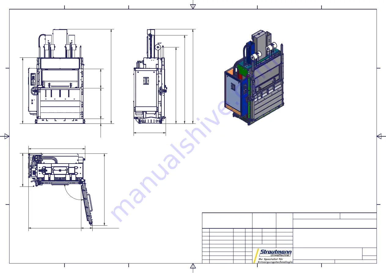
PP1207 PLUS - 215
02.07.2009 Martin.Meyer
1
A3
1:30
1
30
79
28
87
24
92
10
90
2089
15
3
10
02
62
3
100
°
21
50
,0
0
(P
or
ta
lh
öh
e)
Ballenabmessung:
1200 x 1100 x 730 [LxBxH in mm]
Ballengewicht:
bis zu 350 kg *
Kammerinnenmaße:
1200 x 700 x 1397 [BxTxH in mm]
Einfüllöffnung:
1190 x 600 [BxH in mm]
Presskraft:
580 KN
Presshub:
890 mm
Taktzeit:
ca. 37 sek.
Maschinengewicht:
2400 Kg
Motorleistung:
4 KW
Anschlußwerte:
400V / 3 Phasen / 50 Hz
*...Ballengewicht ist materialabhängig
1047
23
42
1850
371
30
81
Summary of Contents for Plus 70
Page 58: ...Appendix V 152 10 11 Rev END 8 2 8 1 Declaration of Conformity...
Page 59: ...Appendix V 152 10 11 Rev END 8 3 8 2 Assembly drawings...
Page 60: ...Appendix V 152 10 11 Rev END 8 4 8 3 Parts list with recommended identified spare parts...
Page 61: ...Appendix V 152 10 11 Rev END 8 5 8 4 Hydraulic diagram parts list...
Page 62: ...Appendix V 152 10 11 Rev END 8 6 8 5 Circuit diagram parts list...
Page 63: ...Appendix V 152 10 11 Rev END 8 7 8 6 Supplier documentation...


