background image

866-795-1586 • WWW.STONEAGETOOLS.COM

6

2” BADGER MODEL AND HEAD INFORMATION

2” BADGER MODELS 

The BA-LKD-P4 / BA-LKD-BSPP4 / BA-LKD-MP6R / BA-LKD-MP9L / 

BA-LKD-MP9R are self-rotating swivels designed for cleaning 2” to 4” 
tubes and lines with bends and long radius elbows, such as U-Tubes 

and process lines. 

The P4 and BSPP4 tools can be used at operating pressures up to 
15,000 psi (1035 bar) and have either a 1/4”NPT or 1/4”BSPP female 

pipe thread inlet. 

The MP6R, MP9L and MP9R tools at up to 22,000 psi (1500 bar). The 

MP6R tool has a 3/8” female right-hand medium pressure inlet.  The 
MP9L tool has a 9/16” female left-hand medium pressure inlet and 
the MP9R has a 9/16” female right-hand medium pressure inlet.  

The tools do not use any bearings, seals, or lubricating fluid.  

Rotation is powered by the jet thrust. 

If a standard 1/4” NPT or BSPP hose end is used, they can pass 
through elbows in 3” and larger lines. If using the tool in 2” line a 
special shorter hose end is required to allow tool to travel through 

elbows. Contact StoneAge for more information on the hose 
requirements. 

An OPTIONAL BA 530 Fairing Assembly is available for all 2” Badger 
models when using hose sizes up to 6mm.  The fairing is designed to 

be attached to the back of the 2” Badger to help prevent the rear edge 

of the tool from getting caught on obstructions during withdrawal from 

tubes or lines.

BA 530 Fairing

7 Ports: 

1 @ 15º 

1 @ 30º 
1 @ 45º 
2 @ 90º 

2 @ 132º

15º

30º

45º

90º

90º

2 x 132º

Port Locations

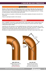
2” BADGER BACKOUT PREVENTION

2” BADGER HEAD CHART

MODEL / INLET 
CONNECTIONS

PRESSURE RANGE

FLOW RANGE

BA 546-LKD-

HEAD

psi

bar

gpm

lpm

BA-LKD-P4

1/4 NPT

BA-LKD-BSPP4

1/4 BSPP 

8-15K

552-1034

11-16

42-61

A

9-12.5

34-47

B

7-9.5

26-36

C

BA-LKD-MP6R

3/8 MP RIGHT 

BA-LKD-MP9L

9/16 MP LEFT

BA-LKD-MP9R

9/16 MPRIGHT

15-22K

1034-1500

16-18.5

61-70

A

12.5-14.5

47-55

B

9.5-11

36-42

C

DETERMINING HEAD TYPE: 

Three different universal head options can meet different pressure and flow configurations. The drilled 
heads eliminate the need for replacing jet inserts. Operators can swap the drilled heads quickly to meet 
the unique demands of each job. Specification assistance is available through one of our StoneAge 
customer service reps at 1-866-795-1586. Or on line at 

www.stoneagetools.com

The chart below is calculated with hose pressure loss from 50 feet of 6 mm or ¼” flex lance.

Summary of Contents for BADGER BA-H6

Page 1: ...BADGER FAMILY SELF ROTARY SWIVELS USER MANUAL EXCLUDES BA H6 4 40K MODEL 2 INCH 4 INCH 6 INCH PL 663 REV P 06 2020...

Page 2: ...INING RISK ASSESSMENT PPE 4 PRE RUN SAFETY CHECK 5 2 BADGER 6 MODEL AND HEAD INFORMATION 6 BACKOUT PREVENTION 7 OPERATION AND TROUBLESHOOTING 8 HEAD REPLACEMENT INFORMATION 9 ASSEMBLY AND PARTS 11 4 B...

Page 3: ...bends and comes with head locking technology for increased safety Head options allow the tool to be optimized for a variety of pump pressures and flows unplug polish or run longer lines based on jetti...

Page 4: ...s and incorporated safety features in the design StoneAge WILL NOT accept responsibility for the results of misuse IT IS THE RESPONSIBILITY OF THE INSTALLER OPERATOR to conduct a job specific risk ass...

Page 5: ...aning Always de energize the system before servicing or replacing any parts Failure to do so can result in severe injury and or death PRE RUN SAFETY CHECK Refer to WJTA IMCA s Recommended Practices Fo...

Page 6: ...the hose requirements An OPTIONAL BA 530 Fairing Assembly is available for all 2 Badger models when using hose sizes up to 6mm The fairing is designed to be attached to the back of the 2 Badger to he...

Page 7: ...BADGER BACKOUT PREVENTION WARNING Because of the short length of the Badger the tool can turn around in large lines and come back at the operator at a high rate of speed If cleaning larger lines a ri...

Page 8: ...e first time to make sure no nozzles are plugged and the jet thrust is correct The Badger should begin to slowly rotate 8 Once operating pressure is reached feed the tool into the line to begin the cl...

Page 9: ...end wrench to remove the Head from the Shaft BA 612 LK TOOL KIT INCLUDES BA 182 Head Removal Tool BA 185 Red Loctite 262 WV 010 Retaining Rings 2 WV 181 Spanner Wrench Loctite is a registered tradema...

Page 10: ...he tapered external surface of the shaft 3 Slip the Removal Tool between the Head and the Body and clamp it into a vise 4 Insert the WV 181 Spanner Wrench into the Shaft 5 Using a 7 8 socket wrench to...

Page 11: ...D C Head NEVER REMOVE SET SCREW FROM HEAD BA 501 LK Shaft BA 503 Body WV 008 O Ring WV 010 Retaining Ring BA 002 P4 15k or BA 002 BSPP4 15K or BA 502 MP6R 22K or BA 502 MP9L 22K or BA 502 MP9R 22K Inl...

Page 12: ...SET OPTIONS Engraved on each head is R12 R18 or R22 this number is the offset of the head that makes it rotate The approximate flow range for each head offset is given in the table pump operating pres...

Page 13: ...being cleaned see below Make sure there is an operator controlled dump in the system operated by the person closest to the cleaning job Follow all operating instructions in this manual DANGER If the 4...

Page 14: ...as well TROUBLE SHOOTING HIGH PRESSURE WATER SEAL LEAK The high pressure seal may leak initially at lower pressures but should pop closed as pressure is increased A continuous leak at operating press...

Page 15: ...lean lint free rags or shop towels Anti Seize Swagelok Blue Goop StoneAge PN GP 043 Blue Goop Grease Chevron Multifak EP1 StoneAge PN GP 049 Isopropyl Alcohol or Denatured Alcohol Blue Goop is a regis...

Page 16: ...nch Shaft Bearing Assembly RJ 011 C Carbide Seat RJ 012 TO H P Seal 5 Use a small screw driver or pick to remove the Retaining Ring from the shaft 6 Pull the Discs and O Rings off of the Shaft DISASSE...

Page 17: ...bearing 9 Remove both Port Plugs from the Head 10 Use a flat head screwdriver to remove the Shaft Seal and inspect for damage Figure 6 For Steps 9 10 8 Use a small pick to remove the O Ring and the S...

Page 18: ...ver the Shaft 4 Place an O Ring on top of this Disc 5 Place an Outer Disc on after the O Ring The external flats of the Outer Discs should be aligned with the flats inside the head 6 Repeat these step...

Page 19: ...nto the center of the Nut with the lip spring side up 11 Install the O Ring in the groove in the bottom of the Nut BAE 002 Nut BAE 030 Wear Ring Shaft Bearing Assembly BJ 026 Port Plug 12 Install the...

Page 20: ...026 Port Plug 1 BJ 048 F Visc Fluid Fast 6oz 1 BJ 062 S Antiseize 2g 1 BRLM 109 Bearing Single Sided 1 PL 663 BADGER Family Manual 1 RJ 011 C Carbide Seat 1 RJ 012 TO H P Seal and O Ring 1 BA 006 Seal...

Page 21: ...x Nozzle 2 x Plug 2 x Nozzle 1 x Plug 2 x Plug 2 x Nozzle Nozzles are Part Number APF4 XXX Plugs are Part Number GP 025 P4SS Once you have confirmed the required jetting configuration use the StoneAg...

Page 22: ...n around in large diameter line VERY DANGEROUS PROPER USE Badger with rigid stinger to prevent turnaround still able to pass through elbows Rigid Stinger 1 1 2 times line ID WARNING Because of the sho...

Page 23: ...e blown into the tool as well TROUBLESHOOTING HIGH PRESSURE WATER SEALS LEAK The high pressure seal may leak initially at lower pressures but should pop closed as pressure is increased A continuous le...

Page 24: ...03 Shaft Adjust Sleeve BA 301 P8 Shaft ADJUSTING SLEEVE DETAIL 1 Open End Wrench for Shaft Sleeve Adjustable Wrench to hold Shaft in place ADJUSTING THE SPEED CONTROL To adjust the speed hold the wren...

Page 25: ...ringe end into the port in the Head and squeeze fresh Viscous Fluid in until clean Viscous Fluid comes out the port in the Nut Hold the tool so the port in the Nut is the highest point If air bubbles...

Page 26: ...sc 5 BA 316 Outer Disc 4 SM 116 O Ring 3 BJ 008 O Ring 3 Figure 3 For Step 4 5 3 Remove the Seat H P Seal and Wave Spring from the bore of the Shaft Figure 1 For Steps 1 2 BA 330 Wear Ring BA 302 Nut...

Page 27: ...Sleeve in order to replace the 2 O Rings Normally it is not necessary to disassemble the Shaft from the Adjust Sleeve Figure 6 For Steps 11 13 9 Remove the Shaft Seal and inspect for damage 10 Remove...

Page 28: ...an O Ring around the outer edge of this Disc 7 Repeat steps 3 through 6 until there are four Outer Discs and five Inner Discs on Shaft Note that there is no outer O Ring on the Inner Discs at each end...

Page 29: ...BJ 026 Port Plug BJ 026 Port Plug 13 Install Shaft Seal into the bore in the Head and the O Ring over threads and into groove of Head 14 Check that the Pins are installed in the Head 12 Install Shaft...

Page 30: ...P9 SERVICE KIT FAST BA 610 P8 MP9 OVERHAUL KIT FAST BA 602 P8 MP9 H P SEAL KIT 1 BA 313 Wave Spring 1 BC 410 Syringe Assembly 1 BJ 011 C Carbide Seat 1 BJ 012 TRO H P Seal and O Ring 1 BJ 026 Port Plu...

Page 31: ...866 795 1586 WWW STONEAGETOOLS COM 31 NOTES PAGE LEFT INTENTIONALLY BLANK...

Page 32: ...NS AS TO THE PERFORMANCE OF ANY PRODUCT EXCEPT AS SET FORTH IN THE STONEAGE LIMITED WARRANTY PROVIDED WITH THE PRODUCT 4 Delivery Seller is not obligated to make delivery by a specified date but will...

Page 33: ...n with such a dispute it shall only be commenced in such courts Seller and Buyer agree to the exclusive jurisdiction of such courts and neither will raise any objection to the jurisdiction and venue o...

Page 34: ...ed by StoneAge will void this Limited Warranty StoneAge reserves the right to change or improve the material and design of the Product at any time without notice to End User and StoneAge is not obliga...

Page 35: ...AMAGES INCLUDING WITHOUT LIMITATION LOSS OF PROFITS LOSS OF GOODWILL DIMINUTION OF VALUE WORK STOPPAGE INTERRUPTION OF BUSINESS RENTAL OF SUBSTITUTE PRODUCT OR OTHER COMMERCIAL LOSS EVEN TO THE EXTENT...

Page 36: ...1 866 795 1586 www STONEAGETOOLS com 2020 StoneAge Inc All Rights Reserved...

Reviews: