STOKVIS ENERGY SYSTEMS ECONOFLAME R30 Installation Operation & Maintenance Download Page 11


Doc653/30CV02A


7

Burner/heat exchanger package [15]

After the gas/air mixture has been correctly mixed, it fl ows into the burner via the inlet channel. 
Due to the overpressure, the gas/air mixture is forced through the burner to the external surface 
of the burner for combustion. 
The heat exchanger is made of smooth stainless steel tubes in the form of coils. It essentially 
consists of two parts; one part is located immediately next to the fl ame, where the major por-
tion of the heat transfer between the combustion gases and the water takes place. The other part 
functions as a condenser for the fl ue gases, where the transfer of latent heat takes place.
Stainless steel water distribution manifolds ensure optimum water fl ow through the heat ex-
changer.

Water connections

These consist of a fl ow connection [4] and a return connection [7]. There is a water temperature 
sensor [16] on the fl ow connection which, apart from controlling the burner load, also monitors 
the water fl ow in the boiler. The latter is done in combination with the fl ue gas temperature sensor  
[8].

Boiler pump [20]

The boiler pump of the types 45, 65 and 85 is located in the return connection of the boiler and 
is electrically connected directly to the corresponding terminals in the control panel. The boiler 
pump of the types 100 and 120 will be delivered separately and can be directly connected to the 
return connection of the boiler. The capacity and the head of the pump are adequate to overcome 
not only the boiler resistance but also some system resistance (see table 1). In the types 45, 65 
and 85, the pump has three-stage modulation, depending on the load.

Condensate drain [13]

The boiler is equipped with a bottle trap. This bottle trap is located on the bottom side of the ap-
pliance and can be easily fi lled with water.

Frame [14]

The frame is the load bearing part of the boiler. All the components are installed on it.
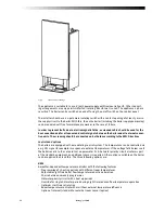
Casing [6]

The casing can be removed easily as one unit. To do this, unscrew the 8 screws found on the top 
and the bottom of the casing.

Electrical equipment

This comprises the control system and safety devices of the boiler. The connection terminals are 
installed in a fully sealed enclosure behind the control panel [21]. This panel can be tilted through 
90° after removing the control panel bolt. This provides access to all the electrical connections, 
without the need to remove the casing. 


2.3 Boiler control 


If heat is required, the boiler will start, if all necessary conditions have been fulfi lled and no 
safety devices have been triggered. This heat requirement will arise if:
- The 

fl ow temperature of the boiler is less than the required fl ow temperature

-  The manual option has been selected using selector switch set to: 

W1

 or 

W2

-   The frost protection has been triggered independently of the operating conditions (

K

q

t

W1

  or 

W2

).

The integrated temperature controller adjusts the heat input inside the boiler by changing the fan 
speed so that the desired temperature is reached and kept at a constant level. Depending on the 
quantity of air displaced by the fan, a specifi c quantity of gas will be added. As a result, the boiler 
capacity can be modulated seamlessly and the heat requirement can be accurately monitored. If 
the fl ow temperature rises above the desired level together with any hysteresis, the boiler will 
switch off. The boiler will start again as soon as the fl ow temperature falls below the desired 
level.  

Summary of Contents for ECONOFLAME R30

Page 1: ...ILERS INSTALLATION OPERATION MAINTENANCE DOCUMENTATION STOKVIS ENERGY SYSTEMS 96R WALTON ROAD EAST MOLESEY SURREY KT8 0DL TEL 08707 707 747 FAX 08707 707 767 E MAIL info stokvisboilers com WEBSITE www...

Page 2: ...r manner whatsoever without the prior permission of Rendamax B V in writing We are engaged in a constant effort to improve our products As a result of this process the products may deviate slightly fr...

Page 3: ...ea 5 2 1 General 5 2 2 Installation 5 2 3 Ventilation 11 5 3 Connections 5 3 1 Gas connection 5 3 2 Electrical connections 5 3 3 Water connections 14 5 3 4 Flue gas outlet and air inlet 5 3 4 1 Connec...

Page 4: ...23 6 5 Setting into operation 25 6 6 Switching off the appliance 6 7 Warnings 7 Commissioning 7 1 General 7 2 Commissioning 26 8 Maintenance 27 8 1 Safety 8 2 General 8 3 Procedure 28 8 4 Cleaning the...

Page 5: ...6 17 20 30 50 Maximum water temperature of central heating system Maximum operating pressure Water content Water resistance T 20 C Excess head of the boiler pump T 20 C C bar litre kPa kPa 90 6 5 1 1...

Page 6: ...00 G R 3 4 R 3 4 R 3 4 R 3 4 R 3 4 L mm 340 405 510 560 670 L1 mm 74 90 90 90 90 W R 11 4 Rp 1 R 11 4 Rp 1 R 11 4 Rp 1 R 11 4 Rp 1 R 11 4 Rp 1 Table 2 Dimensions of the R30 We reserve the right to mak...

Page 7: ...of this documentation You can of course always obtain further information via www stokvisboilers com 1 3 This document The present documentation has been prepared with the following target groups in...

Page 8: ...the boiler is delivered fully wired fully assembled and tested Working principle and design Air is drawn in as required via a speed controlled fan The zero pressure controller of the gas valve measur...

Page 9: ...heating systems with constant ow temperature weather dependent set point adjustment low temperature condensing system external temperature control via building optimiser 0 5 Vdc 10 C 90 C below 1Vdc t...

Page 10: ...ler 11 Automatic boiler controller 21 Control panel 2 2 1 Description of principal components The boiler is made of the following components Fan 9 The fan pulls in and compresses the combustion air dr...

Page 11: ...epending on the load Condensate drain 13 The boiler is equipped with a bottle trap This bottle trap is located on the bottom side of the ap pliance and can be easily lled with water Frame 14 The frame...

Page 12: ...nised installer in accordance with applicable na tional and local standards and speci cations The installation should only be used for heating systems with a maximum water temperature of 90 C It is ex...

Page 13: ...r covered up and should be maintained in a legible condition throughout the life of the appliance Immediately replace damaged or illegible instruction and warning stickers Modi cation The appliance ma...

Page 14: ...ng the winter are in danger of freezing Drain out the water from the lling and drain valve 5 Installation 5 1 Regulations The appliance should be installed by a recognised installer in accordance with...

Page 15: ...3 1 Gas connection The gas connection should be installed by a recognised installer in accordance with applicable national and local standards and speci cations The gas connection is located on the b...

Page 16: ...es according to the EMC Directives Controls and options The boilers are equipped with a modulating control system The temperature can be controlled via a 0 5 Vdc signal for example in response to exte...

Page 17: ...olled hot water re circulation pump Pump kick function DCF receiver for internal clock optional receiver required Communication over a CAN bus Integrated relay and sensor test Can be used in stand alo...

Page 18: ...the ow and return pipes are securely xed with brackets This prevents damage and makes maintenance easier The boiler is an instantaneous boiler and is not suitable for use in open vented systems In suc...

Page 19: ...connection for the air supply is on the top of the boiler The air supply pipe should be airtight This is to prevent the suction of false air Horizontal com ponents in the air supply should be installe...

Page 20: ...is equipped with a premix burner with a fan an overpressure is created in the boiler This overpressure is suf cient to overcome the resistance of the burner the heat exchang er and the chimney The ba...

Page 21: ...Diameter in mm Pipe bend 90 R D 0 5 Pipe bend 90 R D 1 Pipe bend 45 R D 0 5 T piece R30 45 70 80 3 5 4 0 1 4 1 5 1 1 1 2 4 0 4 0 R30 65 80 90 100 4 0 4 5 4 9 1 5 1 7 1 8 1 2 1 3 1 4 4 0 4 5 5 4 R30 8...

Page 22: ...tion should not be adverse ly affected by the use of valves non return valves systems in which several boilers are connected to a common distribution pipe etc The maximum water ow is achieved at t 15...

Page 23: ...1 0 0 5 0 2 Rp 1 Rp 11 4 0 0 5 10 lgpm 0 0 5 1 1 5 2 l s 1 2 3 4 5 6 m3 h m s v 15 20 3 1 5 Wilo TOP S 25 7 Wilo TOP S 30 7 1 230 V Rp 1 Rp 11 4 2 2 2 Q H m Fig 5 Pump characteristics 5 4 1 3 Shut off...

Page 24: ...ordance with the kW rating and system pressure 5 4 3 Water temperature The maximum permissible water ow temperature is 90 C If the limit thermostat is triggered at 97 C the boiler will switch off and...

Page 25: ...in the return line of the secondary part of the system In order to guarantee a properly working system and long life one should remove suspended and corrosive particles by installing a suitable lter s...

Page 26: ...ion at minimum 6 Output status burner load P17 7 Actual required parameter value W2 Service operation at maximum 8 Error code parameter number burner load P9 9 Status inputs Desired load required by t...

Page 27: ...t The new ow temperature will now be active Close the lid Set the required hot water temperature for hot water operation This is only applicable if the hot water mode is being used Open the lid Turn t...

Page 28: ...upted The resistance value measured by the ue temperature sensor lies outside the range of 10 and 126 C Repair the fault and press reset An external safety device connected to the terminals 1 3 has be...

Page 29: ...tion to t B The boiler is out of operation and only comes into operation due to the automatic frost protec tion system Using the rotary selector switch set the type of operation to K C Switch off the...

Page 30: ...lue for full load Reference value for CO2 Types R30 45 R30 65 R30 85 and R30 120 8 8 0 2 for natural gas G20 G25 9 8 0 2 for propane G31 Type R30 100 9 4 0 2 for natural gas G20 G25 10 4 0 2 for propa...

Page 31: ...by using the setting screws Type Diameter of throttle ring R30 45 6 8 mm R30 65 6 0 mm R30 85 6 0 mm R30 100 6 8 mm Remove the measuring equipment and re t the case The boiler is now ready for operat...

Page 32: ...ges Check the combustion Calibrated measuring equipment should be used to carry out gas air and ue gas measurements 8 4 Cleaning the burner and the heat exchanger The burner can be cleaned on both sid...

Page 33: ...7 1 0914 CO easured 2 Conversion factors For NOx N 1 1 ppm 2 05 mg m3 1 759 mg kWh 0 498 mg MJ For CO N 1 1 ppm 1 24 mg m3 1 064 mg kWh 0 298 mg MJ Example Measured values for an environmentally frie...

Page 34: ...oss calori c value o Fuel ef ciency at the nett calori c value CO2 The volume of CO2 in the ue gas O2 The volume of O2 in the ue gas A The quantity of condensed water in the appliance per m3 gas in kg...

Page 35: ...Doc653 30CV02A 31...

Page 36: ...32 Doc653 30CV02A...

Reviews: