6
Doc653/30CV02A
1
2
3
4
5
6
7
14
15
16
17
18
19
20
8
9
10
11
12
13
21
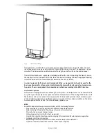
Fig. 3
Overall view
2.2
Main components
1 Flue
outlet
connection
12
On/off
switch
2 Air inlet connection
13 Condensate drain
3 Gas connection
14 Frame
4 Flow connection
15 Burner/ heat exchanger package
5
Automatic
air
vent
16
Water
fl ow temperature sensor
6 Casing
17 Gas valve
7
Return
connection
18
Venturi
8 Flue gas temperature sensor
19 Air intake silencer (tpes 45, 65 and 85)
9 Fan
20 Boiler pump (types 100 and 120 outside
10
Pressure
Gauge
the
boiler)
11 Automatic boiler controller
21 Control panel
2.2.1 Description of principal components
The boiler is made of the following components:
Fan [9]
The fan pulls in and compresses the combustion air, drawn from inside the casing of the boiler.
The fan is a DC current fan equipped with a speed feed-back signal. This speed feed-back signal
is transmitted back to the controller, which makes the necessary corrections.
Gas train
The main component of the gas train is the gas valve [17]. The gas quantity is controlled according
to the quantity of air. The air quantity varies with the speed of the fan. The gas train is equipped
with a test point through which the gas pipe can be vented or the gas inlet pressure can be meas-
ured.
Summary of Contents for ECONOFLAME R30
Page 35: ...Doc653 30CV02A 31...
Page 36: ...32 Doc653 30CV02A...


