51
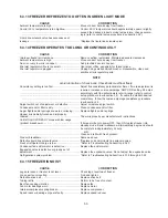
6.3.3 RED CLEAN LIGHT IS FLASHING
CAUSE
CORRECTION
CLEAN was deactivated by depressing the
CLEAN switch; control is awaiting your next
command ...................................................................... Turn power OFF then ON to leave CLEAN mode or depress
...................................................................................... CLEAN again to continue CLEAN m
ode operation.
6.3.4 HOLD READY SWITCH WILL NOT WORK
CAUSE
CORRECTION
The HOLD READY switch has not been held
depressed for 5 seconds to activate or deactivate
HOLD READY mode ..................................................... Depress and keep the HOLD READY switch depressed for 5
...................................................................................... seconds to activate or deactivate HOLD READY mode.
Switch has a loose wire or is defective ......................... Check, repair or replace the switch.
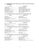
6.3.5 COMPRESSOR WILL NOT START
CAUSE
CORRECTION
Low voltage to unit ........................................................ Determine reason and correct.
Wiring improper or loose .............................................. Check against diagram.
Line disconnect, switch open ........................................ Close start or disconnect switch.
8-Pin relay defective ..................................................... Replace 8-pin relay. (E131 & F131 only)
Compressor contactor defective ................................... Replace contactor.
Start relay failing to close .............................................. Determine reason and correct; replace is defective.
Start capacitor defective ............................................... Determine reason and replace.
Overload protector tripped ............................................ Will reset after cooling.
Overload protector defective ......................................... Replace overload protector. (E111 & F111 only)
Excessively high discharge pressure ............................ *Refer to Troubleshooting Subsection 6.3.18.
Internal mechanical trouble in compressor ................... *Replace compressor.
6.3.6 COMPRESSOR WILL NOT START; HUMS BUT TRIPS ON OVERLOAD
PROTECTOR
CAUSE
CORRECTION
Low voltage to unit ........................................................ Determine reason and correct.
Improperly wired ........................................................... Check wiring against diagram.
Start relay failing to close .............................................. Determine reason and correct. Replace relay if defective.
Capacitor defective ....................................................... Check start/run capacitor. Replace if defective.
Excessively high discharge pressure ............................ *Refer to Troubleshooting Subsection 6.3.18.
Overload protector defective ......................................... Replace overload protector.
Compressor motor has a winding open or
shorted .......................................................................... *Replace compressor.
Internal mechanical trouble in compressor ................... *Replace compressor.
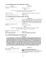
6.3.7 COMPRESSOR STARTS, BUT REMAINS ON START WINDING
CAUSE
CORRECTION
Low voltage to unit ........................................................ Determine reason and correct.
Improperly wired ........................................................... Check wiring against diagram.
Start relay failing to close .............................................. Determine reason and correct. Replace relay if necessary.
Run capacitor defective ................................................ Determine reason and replace.
Excessively high discharge pressure ............................ *Refer to Troubleshooting Subsection 6.3.18.
Compressor motor has a winding open or
shorted .......................................................................... *Replace compressor.
Internal mechanical trouble in compressor ................... *Replace compressor.
Summary of Contents for E131G
Page 1: ...Model E131G F131G SERVICE MANUAL Manual No 513537 3 Mar 2004...
Page 2: ......
Page 14: ...6...
Page 38: ...30 Figure 51 Power Board...
Page 39: ...31 Figure 52 Program Module...
Page 54: ...46...
Page 66: ...58...
Page 68: ...60...
Page 69: ...61 666786...
Page 70: ...62...
Page 71: ...63...
Page 72: ...64...
Page 73: ...65...
Page 74: ...66...
Page 75: ...67...
Page 76: ...68...
Page 77: ...69...
Page 78: ...70...
Page 80: ......

