background image

34

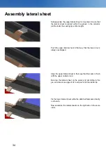
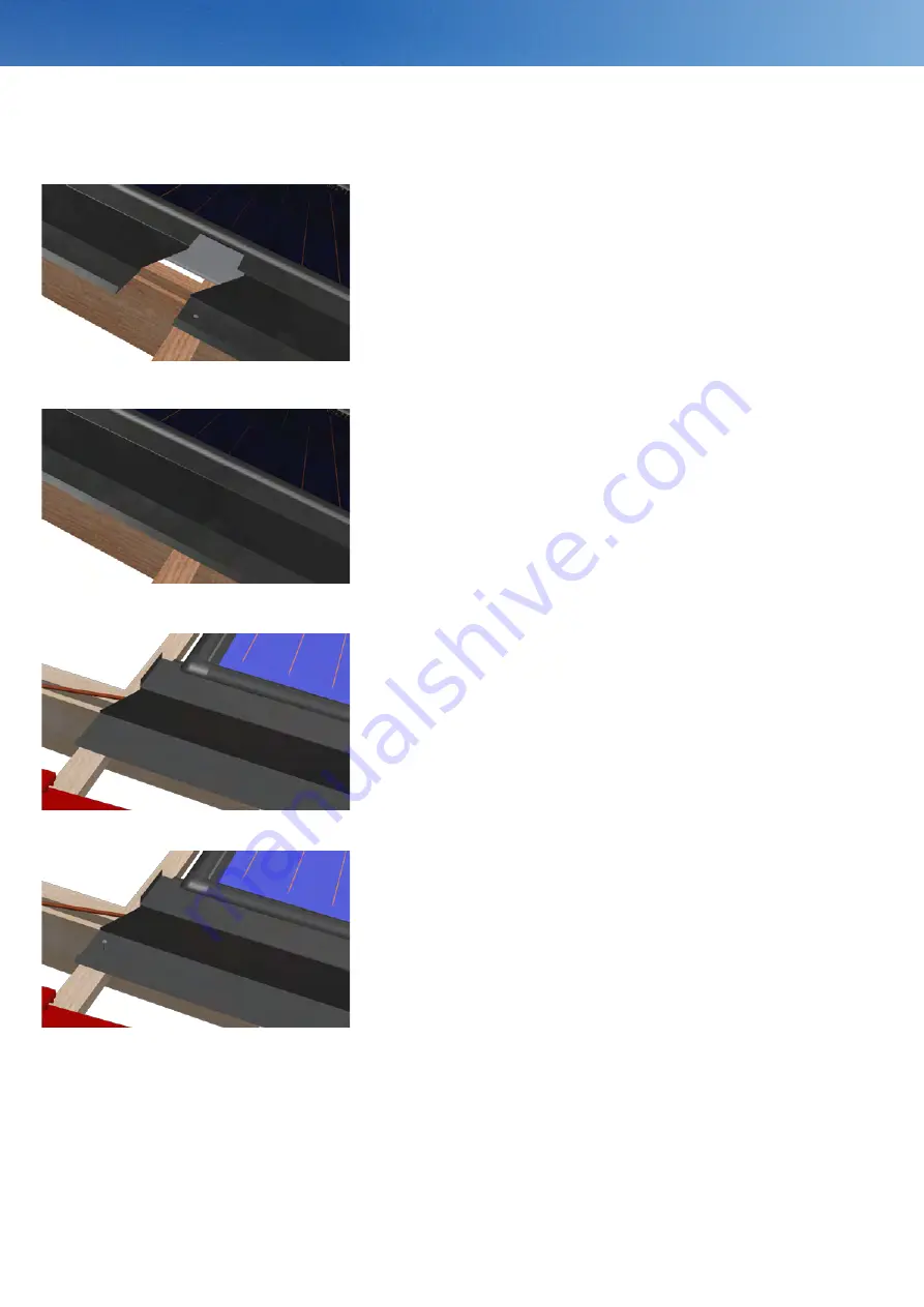
Push the upper lateral sheet in that way that the lower one is 

always overlapped.

Subsequently, the upper lateral sheet is mounted. Ensure that 

the lateral sheet is placed within the groove in the collector 

profile under the sealing lip (entire length).

Assembly lateral sheet

Align the upper lateral sheet in that way that the seam is flush 

with the upper collector end.

Bend up the lateral sheet on the upper end according to the 

pre-cut slots at an angle of 90° and push it till the rubber lip.


Fix the lower lateral sheet withe the attached fasteners directly 

on the lath.

Now assemble the lateral sheets on the right side in the same 

order. 


Summary of Contents for FKF 200

Page 1: ...Assembly instructions Solar collectors FKF 200 240 270 Roof integrated installation...

Page 2: ...he FKA series are marked with the environmental label RAL UZ 73 folar solar collectors Blauer Engel The STI GmbH is obliged to take back the products which are marked with the environmental label RAL...

Page 3: ...e Bereiche und R ume und An lagen im Freien DIN EN 62305 1 VDE 0185 305 Blitzschutz DIN VDE 0105 100 Betrieb von elektrischen Anlagen DIN EN 12976 Thermische Solaranlagen und ihre Bau teile vorgeferti...

Page 4: ...tegration of the installation according to the regulations and for the compliance with safety regulations The operator of the installation is responsible for its opera tion according to the regulatio...

Page 5: ...he following tools are needed for the assembly of the collectors Cordless screwdriver Angle grinder Pencil Drill Saw Chalk box Knife Folding yardstick Hammer Securing devices protec tive equipment Roo...

Page 6: ...eat a heat transfer medium This glycol water mixture gives off the heat to a storage via a heat exchanger The obtained energy can be used for water heating and heating support Sectional model 1 Alumin...

Page 7: ...th 1 777 mm 2 100 mm 2 400 mm 1 200 mm 1 200 mm 1 200 mm Width 1 200 mm 1 200 mm 1 200 mm 1 777 mm 2 100 mm 2 400 mm Height 115 mm 115 mm 115 mm 115 mm 115 mm 115 mm Test pressure 10 bar 10 bar 10 bar...

Page 8: ...section across a collector field Vertical section across a collector field In case of multi row installations the collectors will always be mounted on joint on top of each other The lip collector cov...

Page 9: ...87 9 707 Number of rows 1 2 3 4 5 6 7 8 Field height in mm 2 340 4 680 7 020 9 360 11 700 14 040 16 380 18 720 270 H Number of collectors 1 2 3 4 5 6 7 8 Field width in mm 2 340 4 733 7 126 9 519 11 9...

Page 10: ...Connection BF blue A or B C or D Close unused connections with caps Installations with seven up to 15 collectors in one row Connection bottom left top right BF C F B Connection top left bottom right B...

Page 11: ...9 15 cm Collector field sectional drawing An adjustment of the sheet edging or of the ridge sheet on site is possible upon request Single row collector field Multi row collector field Vertical cross...

Page 12: ...sembly sequence or Single row collector field Multi row collector field When assembling mulit row collector fields the collectors which are located one above the other will be mounted first of all Aft...

Page 13: ...equence or In case of multi row installations the collectors have to be mounted adjoining The lip collector covering of the top collector is set over the lower collector The lip collector covering of...

Page 14: ...subsequently be able to assemble the intermediate sheets without any problems the lip collector covering of the lowest collector has to be cutted out at the respective parts For the assembly of the i...

Page 15: ...will be enabled Assembly of the intermediate plates The assembly of the collectors will be described in the following The assembly of the intermediate plates is described on page 37 When assembling t...

Page 16: ...chnical rules of the attachment point is moved Collektor type measure A measure B measure C for each add row FKF 200 V 2 08 m minimum 20 cm 9 15 cm measure A 1 82 m FKF 240 V 2 33 m minimum 20 cm 9 15...

Page 17: ...ayed down the hydraulical collector connector must be mounted at the concisely overhanging collector connection 1300002 collector connection set hydraulical Insert the hydraulical collector connerctor...

Page 18: ...ully pushed until the hydraulic collector connectors engage into the collector connection The collector connection plates provided ensure the correct distance of the collectors It is importend to ensu...

Page 19: ...h three collector connection plates 1400103 collector connection set roof integrated 2014 1910101 tool set 2014 It must be ensured that the collector connection plates don t lie under a hydraulic conn...

Page 20: ...14 1910101 tool set 2014 Fastening plates After having placed the last collector it has to be fixed with the outer fastening plates at three points This procedure will be repeated for every single sol...

Page 21: ...The measurement deviation of the recorded temperature is 2 K compared with the medium temperature Assembly of the probe Every collector is equipped with a sheath for the positioning of a temperature s...

Page 22: ...etely mounted air eliminator with extension 1310208 Air eliminator set with extension pipe compl with caps The required connection dimension f r the mentioned collector connections has to be calculate...

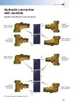
Page 23: ...tion Elbow collecting pipe connection T double collecting pipe connection Elbow collecting pipe connection T double collecting pipe connection T double collecting pipe connection Hydraulic connection...

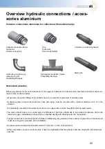
Page 24: ...llector connection 22 mm for soldered fittings or clamping ring joints Smart Lock System Collector connection hydraulic compensator which connects two collectors and compensates thermal dilations Smar...

Page 25: ...ssary that neither brass slivers nor copper slivers will be brought into the hyraulic system The solar collector has to be a closed system Additional air inlet from outside has to be avoided mandatori...

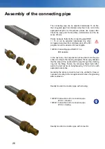
Page 26: ...components will be slided onto the pipe ends according to the drawing alongside Please pay attention that the pipe will be pushed all the way through the clinching ring into the fitting Fasten the scr...

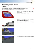
Page 27: ...e assembly of the plate set starts definitively with the left eaves sheet The following eaves sheets must be pushed on the left into the respective previously mounted eaves sheet Push the eaves sheet...

Page 28: ...fter clicking and aligning the left eaves sheet fix it with the three supplied glands in the pre punched holes 1910001 tool set Where the lateral sheet has an overhang fixate the eaves sheet with a na...

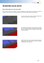
Page 29: ...h the attached sealing screws in the collector frame Therefor use the pre punched holes in the eaves sheet Eaves sheet extension or eaves sheet right When mounting more than two collectors in one row...

Page 30: ...xample slate shingle or Prefa can be installed to support the eave plate can be installed an additional lath under the eave plate Flat roof tiles with a maximum of 15mm profiling where the grooved rol...

Page 31: ...recisely with the lip collector covering When assembling the distance metal sheets please pay attention to the waterflow from the upper to the lower distance metal sheet top bottom To avoid injury it...

Page 32: ...aves sheet on the top or below In case of vertical collectors use two lateral sheets per row left and right In case of horizontal collectors use one lateral sheets per row left and right Start the ass...

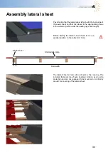
Page 33: ...extra protection and are not supposed to be mounted on or directly around the covering of the lateral sheet Pay attention that the lateral sheet is flush with the bent edge of the eaves sheet and that...

Page 34: ...r the sealing lip entire length Assembly lateral sheet Align the upper lateral sheet in that way that the seam is flush with the upper collector end Bend up the lateral sheet on the upper end accordin...

Page 35: ...the measures in the table above If there is no lath on the rest of the support sheets install one additionally Assembly dimensions support sheet ridge sheet connection bottom part Fix the support shee...

Page 36: ...er the sealing lip Ensure that the support sheets are not slipping during the assembly Completely mounted ridge sheet left Pay attention that the ridge sheet engages completely audibly over the EPDM p...

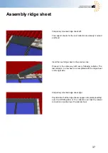
Page 37: ...and that the lateral connection is pushed over the lateral sheet Insert the next ridge sheet in the previous one Proceed in the same way with every following collector The last collector in a row has...

Page 38: ...directly next to the seam Ensure that the ground sheet is dry dust and dirt free during the whole application Depending on the type of roof covering the application of the sealing wedges may not be n...

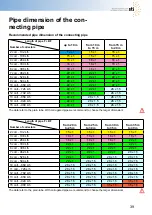
Page 39: ...90 L h 28 x 1 5 28 x 1 5 35 x 1 5 35 x 1 5 Pipe dimension of the con necting pipe Recommended pipe dimension of the connecting pipe Length of pipe F BF Number of collectors up to 10 m from 10 m to 15...

Page 40: ...22 x 1 22 x 1 22 x 1 22 x 1 7 coll 462 L h 28 x 1 5 28 x 1 5 28 x 1 5 28 x 1 5 8 coll 528 L h 28 x 1 5 28 x 1 5 28 x 1 5 28 x 1 5 9 coll 594 L h 28 x 1 5 28 x 1 5 28 x 1 5 28 x 1 5 10 coll 660 L h 28...

Page 41: ...ry to make sure that the back flow temperature is never lower than the ambient tem perature If necessary take appropriate measures e g increase of back flow temperature to at least 30 C Regular inspec...

Page 42: ...sis Date of commissioning Remarks Heat transfer medium Date of assembly General system checkpoints Maximum temperature Temperature difference Setting value Control value Type Programme tick accordingl...

Page 43: ...43 Initial operation Schematic drawing of the system construction and piping scheme...

Page 44: ...44 Initial operation Schematic drawing of the system construction and piping scheme...

Page 45: ...45 Notes Initial operation...

Page 46: ...46 Notes Initial operation...

Page 47: ...zed changes on the collectors and the accessories There is no guarantee or warranty due to optical or technical reduction or defects on the collector resulting from external influences forasmuch as th...

Page 48: ...yright 2017 Version 03 2017 STI Solar Technologie International GmbH Seiferitzer Allee 14 08393 Meerane GERMANY Tel 49 03764 795610 Fax 49 03764 7956115 E Mail info sti solar de Homepage www sti solar...

Reviews: