


2.
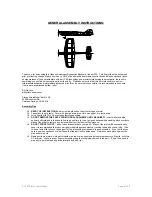
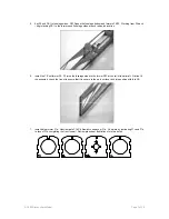
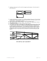
Study the following diagram for information regarding optional GWS drive systems support motor sticks required
(not supplied with the model) Use of the GWS EPS, LPS, or IPSD systems will require removing material from
the firewall former F1. Frame the model as instructed then remove material from F1 accordingly to fit your
favorite GWS drive:
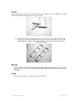
EPS Drive Cut
Along Etch Lines
OPTIONAL GWS DRIVE SYSTEM SUPPORT
IPS-D
LPS
IPS-D
LPS
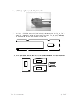
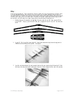
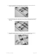
3.
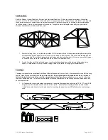
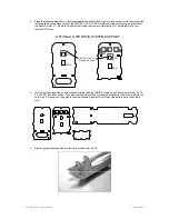
Lay one-half fuselage side on a flat surface with the lettering “INSIDE” facing up and gently work former F2, F3,
F4, and BT1 tray into position. Tack glue formers into position by wicking a small drop of CA onto a tab joint on
each side. Only apply enough glue to tack the assembly together we still want the parts to have the ability to
shift.
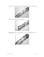
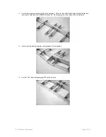
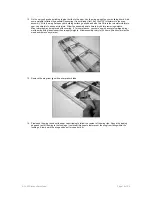
4.
Attach opposite fuselage side and tack into position with thin CA.
© 2003 Stevens AeroModel.
Page 6 of 20