
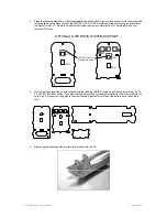
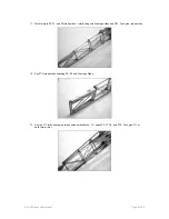
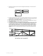
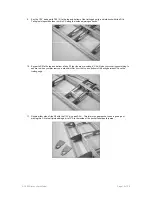


17. Install battery hatch supports H3a, H3b, and H3c to fuselage sides within battery box. Refer to plan sheet for
details on placement.
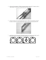
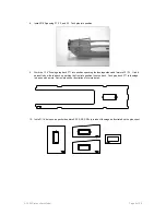
18. Assemble the tail skid from 1/32” ply parts T1 (2) , and T2 the ply skid parts will capture the 1/32” wire skid (bent
to shape using the plan sheet as a guide). Do not attach the skid assembly to the fuselage until after you have
covered the model. – see plan sheet for more detail.
19. Double all tack glued joints by flowing a small amount of thin CA along adjoining surfaces.
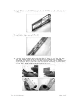
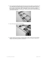
20. Using a sanding block, gently final sand the fuselage – sand a slight taper to the fuselage tail post to allow for a
fluid transition to the rudder.
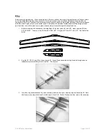
21. Test fit tail feathers to fuselage sand lightly if required to achieve a positive fit.
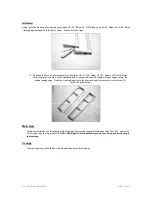
22. Follow illustrations on plan sheet for routing the two 1/32” ID plastic tubes through the fuselage at former F5 and
F7 for guiding the rudder pull/pull cable.
The tubing should be installed prior to covering the model!
Allow
the pull-pull guide tube to extend aft of former F7 by ½” as illustrated on the plan sheet. Using thin CA glue
secure the pull/pull tubing to the balsa structure. The remaining detail for the install and setup of this system is
located on the plan sheet. NOTE: it helps to pre-harden the holes in formers F5 and F7 with thin CA prior to
installing tubing cut a 45 degree bevel in one end of the tubing to allow it to facilitate snaking the tube through
the holes in each former. The rudder gets two tubes that should exit on either side of the fuselage just aft of
former F7.
SEE DETAIL ON PLAN SHEET
© 2003 Stevens AeroModel.
Page 11 of 20