


7-4
764333-098
when removing clamps and replacing squeeze
tube. Residual detergent might remain in used
squeeze tube. If detergent contacts skin or eyes,
immediately flush with running water for at least
10 minutes. If contact was with the eyes, seek
medical attention.
1. Lock building electrical supply disconnect switch
in OFF position and close unit supply valves.
2. Remove two screws attaching pump cover to pump
head. Lift cover away from head.
3. Pulling on one end of squeeze tube, pull tube out of
pump head.
4. Using an Allen hex key, remove setscrew. Lift roller
block out of head.
5. Remove two screws holding head in place. Pull
head away from pump motor.
NOTE: Make note of electrical connections for reas-
sembly.
6. Unplug pump and remove two screws attaching
base of pump assembly to bracket. Remove pump
assembly from detergent compartment.
7. Untighten nut holding ground to motor.
8. Disconnect all electrical connections from the
motor.
9. Remove two screws fastening motor to pump
assembly base.
CAUTION – POSSIBLE EQUIPMENT DAM-
AGE: Ensure a cooling fan is attached to rear
motor shaft. Check that the fan blades are posi-
tioned to send airflow to motor. Motor will overheat
without a cooling fan.
10.Remove propeller and install on new motor.
11.Attach new motor to pump assembly with screws
previously removed.
12.Reconnect all electrical connections.
13.Tighten nut holding ground to motor.
14.Plug pump and secure with two screws previously
removed.
15.Reinstall head and secure with two screws previ-
ously removed.
CAUTION – POSSIBLE EQUIPMENT DAM-
AGE: Carefully tighten setscrew. Metal set-
screw can easily strip plastic threads in roller block
assembly.
16.Reinstall roller block and secure with set screw
previously removed.
17.Reinstall squeeze tube.
18.Reinstall pump cover to pump head kit with two
screws previously removed.
19.Initiate a cycle and check pump motor operation.
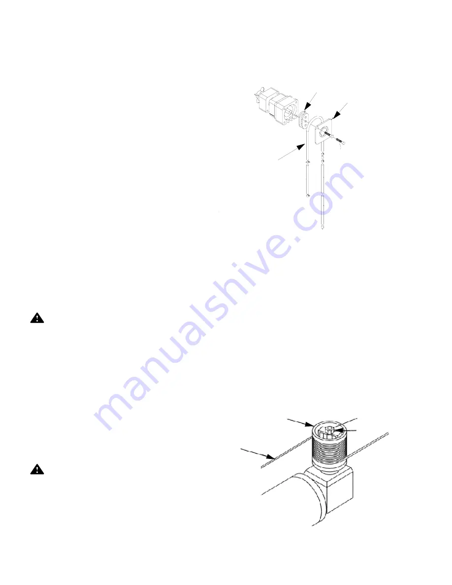
7.5 CARRIAGE DRIVE
7.5.1 Adjusting Carriage Drive Clutch
1. Set POWER-OFF/STANDBY switch to OFF/
STANDBY. Lock disconnect switch in OFF position
and close building supply valves.
2. Remove safety cover from top of drive motor cap-
stan.
3. Loosen setscrews on 3/4" adjusting nut located in
center of capstan (see Figure 7-4).
4. Tighten adjusting nut in 1/16 turn increments until
carriage moves smoothly back-and-forth.
5. Tighten setscrews and replace safety cover.
6. Re-energize washer utilities.
Figure 7-3. Replace Pump Motor
Roller Block
Pump Cover
Squeeze Tube
Figure 7-4. Drive Clutch
Capstan
Cable
Adjusting
Nut
Summary of Contents for Basil 4700
Page 1: ...MAINTENANCE MANUAL Basil 4700 Cage and Rack Washer 2008 10 15 P764333 097 ...
Page 3: ...OPERATOR MANUAL Basil 4700 Cage and Rack Washer 2008 08 14 P920509 645 ...
Page 172: ...2 764333 099 Figure 1 Basil 4700 Cage and Rack Washer Inside Washer Inside Inside Washer ...
Page 174: ...4 764333 099 Figure 2 Cabinet Assembly Left Side Control Shown ...
Page 176: ...6 764333 099 Figure 3 Sump and Floor Grating Assembly ...
Page 178: ...8 764333 099 Figure 4 Door Assembly ...
Page 180: ...10 764333 099 Figure 5 Double Door Interlock System ...
Page 182: ...12 764333 099 Figure 6 Interior Light ...
Page 184: ...14 764333 099 Figure 7 Safety Emergency Stop Cable Assembly ...
Page 186: ...16 764333 099 Figure 8 Spray Header Assembly ...
Page 188: ...18 764333 099 Figure 9 Cable and Roller Assembly DETAIL A DETAIL B See Detail A See Detail B ...
Page 192: ...22 764333 099 Figure 11 Automatic Water Rack Flush System For Two Racks Option ...
Page 194: ...24 764333 099 Figure 12 Damper 1 ...
Page 196: ...26 764333 099 Figure 13 Exhaust Fan ...
Page 198: ...28 764333 099 Figure 14 Hot Water Line Components 6 5 4 10 10 7 8 9 7 ...
Page 200: ...30 764333 099 Figure 15 Cold Water Line Components ...
Page 202: ...32 764333 099 Figure 16 Recirculation Piping ...
Page 204: ...34 764333 099 Figure 17 Steam Line Components ...
Page 206: ...36 764333 099 Figure 18 Final Rinse System Assembly ...
Page 210: ...40 764333 099 Figure 20 Pneumatic Block ...
Page 212: ...42 764333 099 Figure 21 Peristaltic Chemical Injection Pumps ...
Page 214: ...44 764333 099 Figure 22 Solution Tank 25 ...
Page 216: ...46 764333 099 Figure 23 Tank Support Frame ...
Page 218: ...48 764333 099 Figure 24 Guaranteed Cooldown Tank ...
Page 220: ...50 764333 099 Figure 25a Electrical Box and Control Column Assembly ...
Page 226: ...56 764333 099 Figure 26 Control Panel See Detail A DETAIL A ...
Page 228: ...58 764333 099 Figure 27 Seismic Tie Down Anchorage Option ...
Page 230: ...60 764333 099 Figure 28 Bottle Washing Cart WA02 010 ...
Page 232: ...62 764333 099 Figure 29 Bottle Washing Cart WA02 020 ...
Page 234: ...64 764333 099 Figure 30 Pan Cart WA02 030 Accessory ...
Page 236: ...66 764333 099 Figure 31 Universal Cage and Pan Wash Cart WA03 100 7 ...
Page 238: ...68 764333 099 Figure 32 Universal Cage Wash Cart WA02 040 ...
Page 240: ...70 764333 099 Figure 33 Cart Tilt Ramp WA02 050 ...
Page 242: ...72 764333 099 Figure 34 Floor Ramp for Floor Mounted Units WA02 060 ...
Page 244: ......
Page 245: ......
Page 246: ......
Page 247: ......
Page 248: ......
Page 249: ......
Page 250: ......
Page 251: ......
Page 252: ......
Page 253: ......
Page 254: ......
Page 255: ......
Page 256: ......
Page 257: ......
Page 258: ......
Page 259: ......
Page 260: ......
Page 261: ......
Page 262: ......
Page 263: ......
Page 264: ......
Page 265: ......


