


TV6.2
21
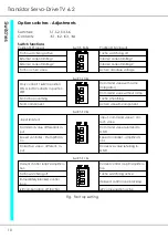
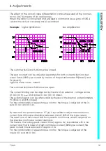
4 Adjustments
Adjustments -
Enable
The control advise is provided as general information and it is not obligatory.
The local regulations and the connection and operating instructions must be
adhered to.
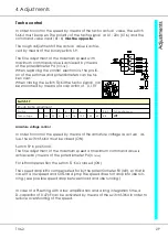
Connectors
X1: 2ac to X1: 32c
Terminals
X1: 1 to X1:16
X2 : 17 to X2 : 26
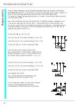
When connecting X1:32c (X1:1) to X1:30c (X1:2) or applying a voltage superior
to +10V, the command value and the speed controller (RVU) will be enabled
immediately.
When opening the contact or switching off the enable voltage the command
value is immediately set to 0 and the speed controller drive is disabled after 2s
(emergency stop).
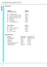
Output
X1:32c (X1: 1) 15V/6mA
Input
X1:30c (X1:2)
Input resistance 4kΩ
Note:
Contact current 6mA
Relays with gold contacts or Reed relays
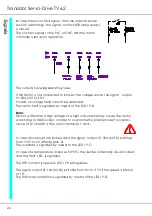
Input X1:18c (X1: 8) device ground GND
Input X1:30c (X1:2) enable input
Input resistance 4kΩ
Drive enable voltage from a PLC or CNC
+10V to +30V (n24V/6mA)
If relay contacts are employed in the enable line,
appropriate contacts must be provided.
Summary of Contents for TV 6.2
Page 12: ...Transistor Servo Drive TV 6 2 12 ...
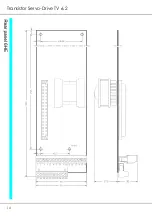
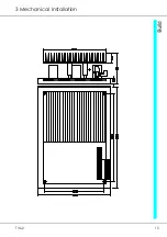
Page 13: ...TV6 2 13 3 Mechanical Installation ...
Page 14: ...Transistor Servo Drive TV 6 2 14 ...
Page 15: ...TV6 2 15 3 Mechanical Installation ...
Page 17: ...TV6 2 17 4 Adjustments Anschluss Kompaktgerät Anschluss Mehrachskombination ...
Page 38: ...Transistor Servo Drive TV6 2 38 ...
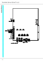
Page 39: ...TV6 2 39 8 Circuit Diagrams ...
Page 40: ...Transistor Servo Drive TV6 2 40 ...
Page 41: ...TV6 2 41 8 Circuit Diagrams ...