


Transistor Servo-Drive TV6.2
28
T
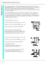
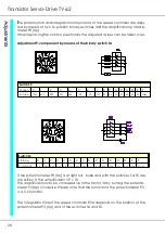
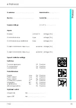
he proportional and integration components of the speed controller are adjus-
ted by means of two 16-position binary switches and the amplification potentio-
meter P3 (Xp) .
When replacing the control electronics the adjusted values can be taken over.
Adjustment P-component by means of the binary switch S4
Switch S4
Position
0
1
2
3
4
5
6
7
8
9
A
B
C D E
F
R-value
1000
450
280
209
180
148
123
107
90
82
73
67
64
59
55
52k
If the potentiometer P3 (Xp) is at right full scale and with the switches S4/S5 are
in position 0, the amplification VP = 10.
The amplification can be increased up to the factor 30 by turning the potentio-
meter P3 (Xp) clockwise. Please note that the function of the potentiometer P3
is a 1/x function.
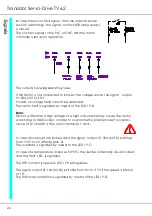
The integration time of the speed controller RVU depends on the position of the
potentiometer P3 (Xp) and of the switches S4 and S5.
Switch S5
Stellung
0
1
2
3
4
5
6
7
8
9
A
B
C
D
E
F
C-value µF
0,01
0,02
0,03
0,04
0,06
0,07
0,08
0,09
0,11
0,12
0,13
0,14
0,15
0,16
0,18
0,19 µF
Summary of Contents for TV 6.2
Page 12: ...Transistor Servo Drive TV 6 2 12 ...
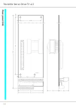
Page 13: ...TV6 2 13 3 Mechanical Installation ...
Page 14: ...Transistor Servo Drive TV 6 2 14 ...
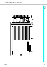
Page 15: ...TV6 2 15 3 Mechanical Installation ...
Page 17: ...TV6 2 17 4 Adjustments Anschluss Kompaktgerät Anschluss Mehrachskombination ...
Page 38: ...Transistor Servo Drive TV6 2 38 ...
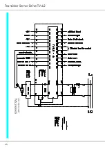
Page 39: ...TV6 2 39 8 Circuit Diagrams ...
Page 40: ...Transistor Servo Drive TV6 2 40 ...
Page 41: ...TV6 2 41 8 Circuit Diagrams ...


