
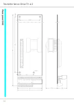


TV6.2
27
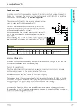
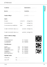
4 Adjustments
An ammeter for the armature current
can be connected to the terminals
X1:26a (X2:20) and X1:18a (X2:24).
The output voltage is ±5V for ±200%
type current.
The output resistance is 1kΩ .
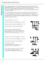
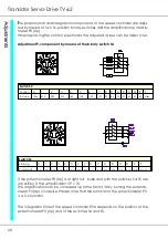
The command value input can be switched as a differential input or as an input
amplifier with reference to point zero, depending on how the switch S2:K2 is
switched.
S2:K2 closed (ON)
= input with reference to point zero
(X1: 8a connected to X1: 8 GND)
S2:K2 open (OFF)
= differential input
Amplification of the input amplifier = 1
The command value at the output of the differential amplifier can be measu-
red across X4:1.
A correction value can be added to the speed controller using the additional
input (2
nd
command value). The switch S2:K2 can be used to adjust whether the
additional input has reference to zero or is on the same potential as the differ-
ential amplifier.
S2:K2 closed (ON)
= input with reference to point zero
S2:K2 open (OFF)
= differential input
The amplification of the additional input can be varied from 0 to 100% by me-
ans of the internal potentiometer P9.
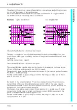
The integration time of the slope limiting device is adjusted by means of the po-
tentiometer P1 (INT). The time until the max. actual value applies across the out-
put can be extended by turning the potentiometer clockwise.
Time with the potentiometer at left full scale
= 0.1s
Time with the potentiometer at right full scale
= 4.5s
The integrator function can be measured at PIN X4:2 with the enable switch clo-
sed.
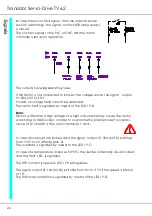
The command value with or without integrator function is switched to the
speed controller by using the switches S3:K1 and S3:K2.
S3:K1 ON, S3:K2 OFF
= with integrator
S3:K1 OFF, S3:K2 ON
= without integrator
Summary of Contents for TV 6.2
Page 12: ...Transistor Servo Drive TV 6 2 12 ...
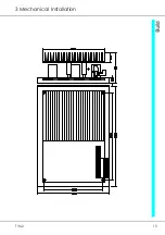
Page 13: ...TV6 2 13 3 Mechanical Installation ...
Page 14: ...Transistor Servo Drive TV 6 2 14 ...
Page 15: ...TV6 2 15 3 Mechanical Installation ...
Page 17: ...TV6 2 17 4 Adjustments Anschluss Kompaktgerät Anschluss Mehrachskombination ...
Page 38: ...Transistor Servo Drive TV6 2 38 ...
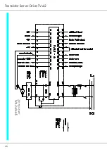
Page 39: ...TV6 2 39 8 Circuit Diagrams ...
Page 40: ...Transistor Servo Drive TV6 2 40 ...
Page 41: ...TV6 2 41 8 Circuit Diagrams ...


